P2P network system

a network system and peertopeer technology, applied in the field of peertopeer network system, can solve the problems of server bottleneck in the client/server model, server overload state, server overload, etc., and achieve the effect of preventing unauthorized access

Inactive Publication Date: 2005-09-29
FUJITSU LTD
View PDF7 Cites 82 Cited by
  • Summary
  • Abstract
  • Description
  • Claims
  • Application Information

AI Technical Summary

Benefits of technology

[0025] An object of the present invention is therefore to provide a technique with which as to divided files of a share target file that are held in multiple peer nodes constituting a P2P network, it is possible to prevent the peer nodes holding the divided files from being identified, thereby preventing unauthorized access.

Problems solved by technology

In recent years, however, along with the widespread proliferation of Always On broadband lines, the improvements of the performances of personal computer, and the increases of the disk capacities (storage capacities) of the personal computers, there occur server bottleneck problems in the client / server model (client / server type communication network).
As a result of the widespread proliferation of the Internet, which was started by the public use of the WWW, however, the mutual connection form has been lost because it becomes sufficient that each computer operates as a client and it becomes unnecessary for the computer to function as a server.
However, it is not a rare case where access is concentrated on popular sites and therefore servers fall into an overload state or networks are congested.
This mode depends on the central server, so that there is a disadvantage in that the network is stopped at the time of server down but there is an advantage in that information management becomes easy.
This mode does not depend on any central server, so that there is a disadvantage in that the management of the node information and the like becomes complicated but there is an advantage in that even if a network is stopped partially, the network will never be stopped entirely.
In the client / server model, the file server rejects the access by each unauthorized user by using the user authentication technology, although the shared files are collectively managed in a stationary manner, so that once unauthorized access is performed, this results in a situation where a large number of files are leaked.
Even in this case, however, there still remains a possibility that like in the case of a file server, files will be leaked through unauthorized access.
Also, even if the leaked files are encrypted, there is a possibility that the files will be decrypted.

Method used


Image

  • P2P network system
  • P2P network system
  • P2P network system

Examples


first specific example

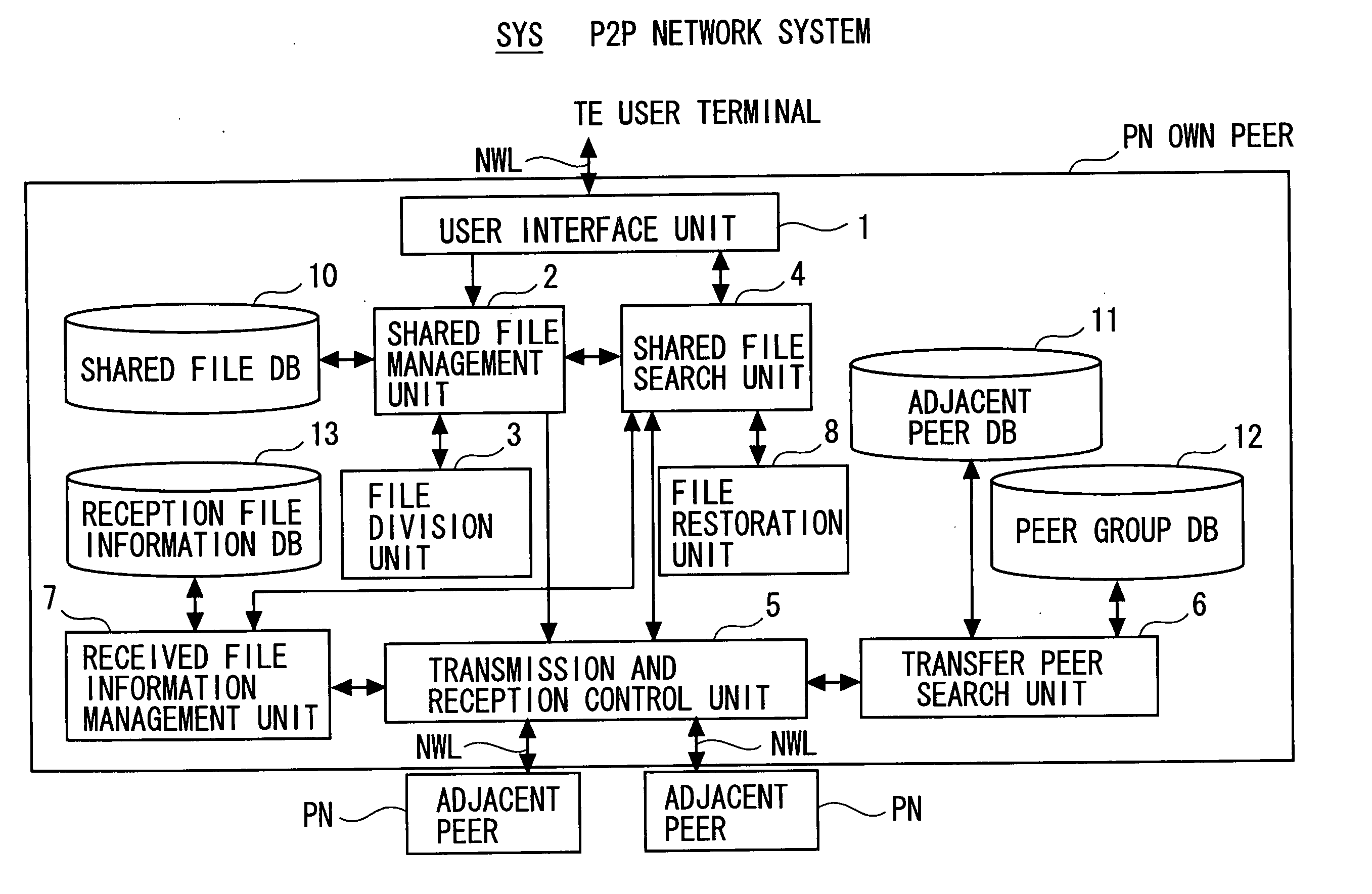
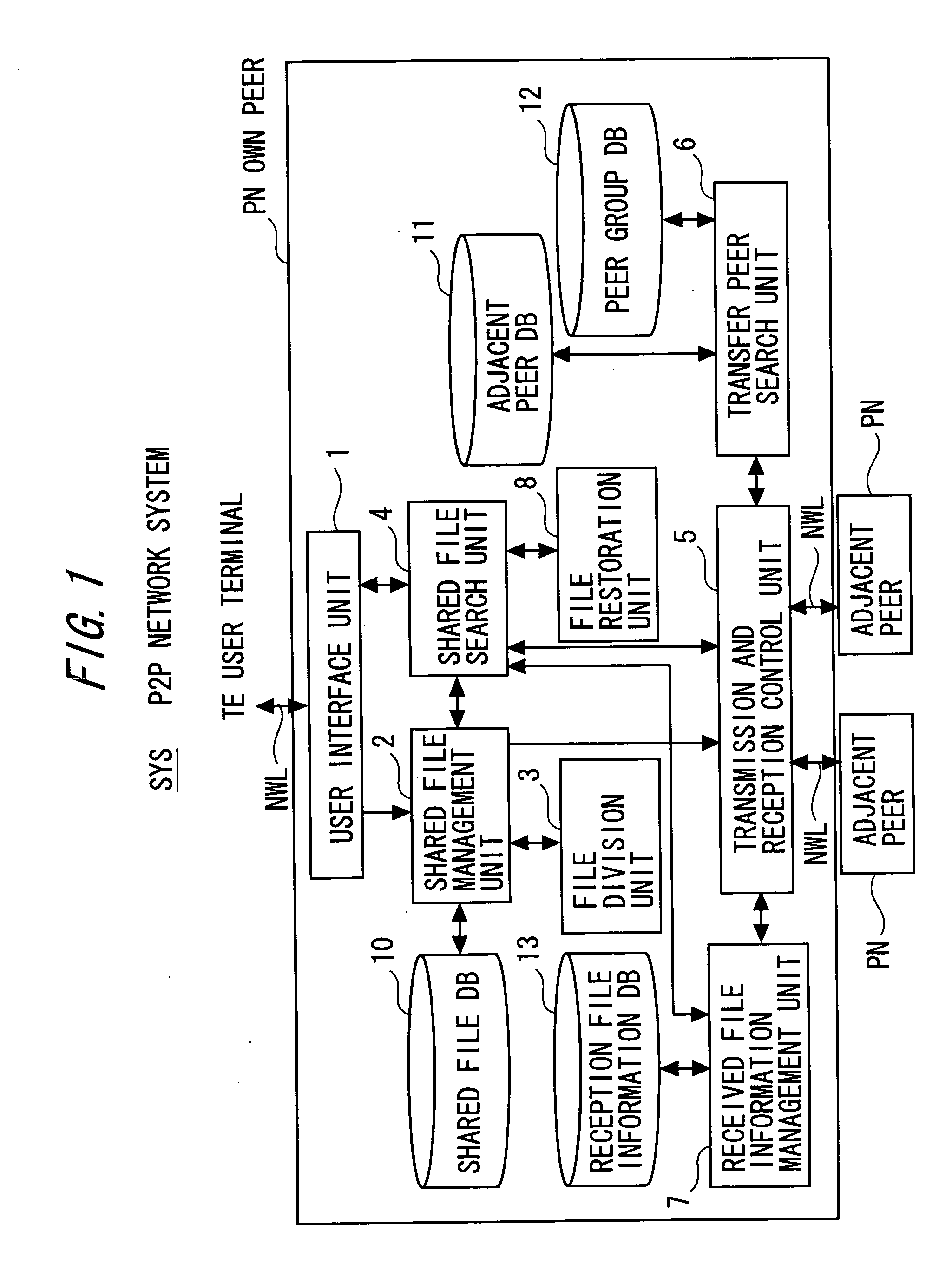
[0078] Next, a first specific example in the P2P network system SYS according to one embodiment of the present invention shown in FIG. 1 will be described.

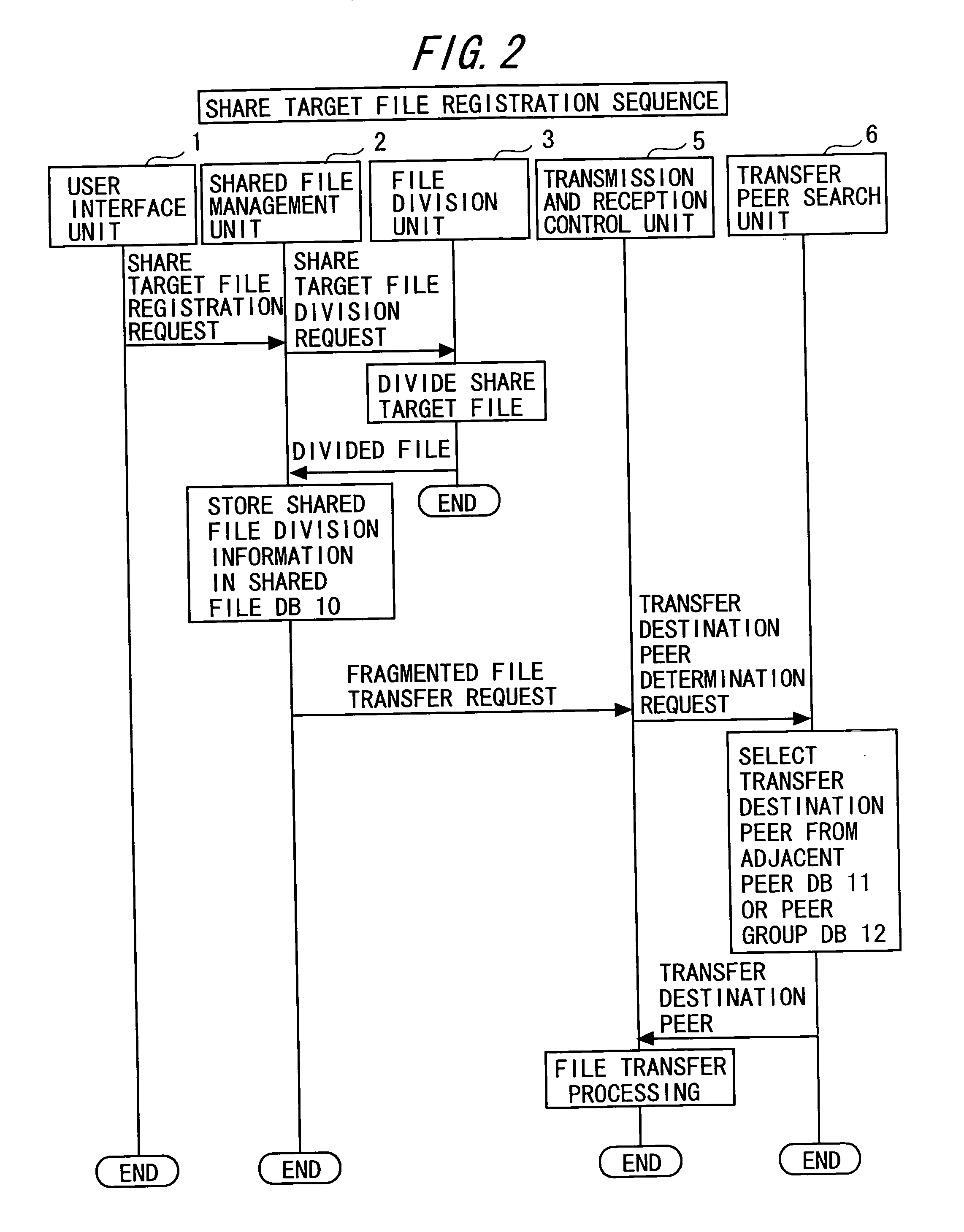
[0079] As the first specific example, a file division and sharing technique will be described with which under a condition where the multiple peers PN are not grouped, a share target file (file to be shared) is divided / transferred and shared in the P2P network NW allowing peer-to-peer type communication between the multiple peers PN.

[0080] This file division and sharing technique will be described with reference to a construction of the P2P network NW shown in FIG. 5, a construction of the shared file DB 10 shown in FIG. 6, a construction of the adjacent peer DB 11 shown in FIG. 7, and a construction of the reception file information DB 13 shown in FIGS. 8 and 9 as well as FIGS. 1 to 4.

[0081] In this example, it is assumed that the peer A divides a share target file, thereby starting processing for sharing the file. Also, it is...

second specific example

[0109] Next, a second specific example in the P2P network system SYS according to one embodiment of the present invention shown in FIG. 1 will be described.

[0110] As the second specific example, a file acquisition technique will be described with which a file divided / transferred and shared with the same file division and sharing technique as in the first specific example described above is searched for and acquired. Like in the first specific example, this second specific example will be described under a condition where the multiple peers PN in the P2P network NW allowing peer-to-peer type communication between the multiple peers PN are not grouped.

[0111] The file acquisition technique will be described with reference to a construction of the P2P network NW shown in FIG. 10, a construction of the shared file DB 10 shown in FIG. 11, a construction of the adjacent peer DB 11 shown in FIG. 12, and a construction of the reception file information DB 13 shown in FIG. 13 as well as FIG...

third specific example

[0132] Next, a third specific example in the P2P network system SYS according to one embodiment of the present invention shown in FIG. 1 will be described.

[0133] As the third specific example, a file division and sharing technique will be described with which under a condition where the multiple peers PN are grouped, a share target file (file to be shared) is divided / transferred and shared in the P2P network NW allowing peer-to-peer type communication between the multiple peers PN. In this example, multiple groups of the multiple peers PN are formed (grouping of the peers is performed) in the P2P network NW and each divided file is sequentially transferred in one of the multiple groups. Each peer PN belongs to only one group and is incapable of belonging to multiple groups.

[0134] This file division and sharing technique will be described with reference to a construction of the P2P network NW shown in FIG. 14, a construction of the shared file DB 10 shown in FIG. 15, a construction...


PUM


Abstract

A peer node according to the present invention relates to a peer node for constructing a peer-to-peer (P2P) network allowing P2P type communication. The peer node includes a unit dividing a share target file for information sharing through the P2P network into a plurality of divided files in a form where contents of each divided file makes no sense by itself; a unit distributing and arranging the plurality of divided files to and in a plurality of peer nodes including the own peer node and at least one other peer node constituting the P2P network; and a unit moving each of the divided files of distribution and arrangement between the plurality of peer nodes at a certain period of time.

Description

BACKGROUND OF THE INVENTION [0001] The present invention relates to a P2P (peer-to-peer) network system having a function of maintaining the security of a shared file, and more particularly to a technology for maintaining the security of a shared file (share target file) held in peers (peer nodes or peer computers) constituting a P2P network for information distributed sharing under a collaboration P2P application environment that supports collaboration between multiple users on the P2P network and realizes efficient collaboration. [0002] Generally, communication through the Internet is carried out between clients and servers. In the case of browsing of Web (World Wide Web (WWW)) pages, for instance, personal computers that are attempting to browse the Web pages are the clients and computers holding the Web pages to be displayed are the servers (Web servers). The servers wait for access from the clients at all times and communication is started by connection from the clients to the ...

Claims


Application Information

Patent Timeline
Patent Type & Authority Applications(United States)
IPC IPC(8): G06F21/62G06F7/00G06F12/00G06F12/14G06F13/00G06F15/00G06F17/30H04L29/06H04L29/08
CPCG06F17/30206H04L63/0428H04L63/08H04L67/108H04L67/06H04L67/1072H04L67/104G06F16/1834
Inventor AOYAGI, YOSHIOIWASAKI, TAKASHINAKAMURA, KATSUICHINOMIYAMA, SEIJIIMAHASE, AKIRA
Owner FUJITSU LTD
Why Eureka
Try Eureka