
Novel CORDIC circuit

a cordic circuit and cord technology, applied in the field of new cordic circuits, can solve the problems of increasing the size of the circuit, increasing the manufacturing cost and operating speed, and complicated design of the whole circuit, so as to save manufacture costs, enhance the operation speed, and simplify the cordic operation

Inactive Publication Date: 2005-09-29
KUEI ANN WEN
View PDF3 Cites 10 Cited by
  • Summary
  • Abstract
  • Description
  • Claims
  • Application Information

AI Technical Summary

Benefits of technology

[0010] The objective of this invention is to provide a novel CORDIC circuit to simplify the CORDIC operation, to enhance the operational speed and to save the manufacture cost.

Problems solved by technology

Due to the fact that the circuit of the multiplier is comparatively complicate, the use of a plurality of multiplier will make the whole circuit complicated in design and large in size, rendering the result of higher manufacture cost and lower operational speed.
Components used in the operation of complex numbers will further increase the size of the circuit, while precision of such calculation is limited.
However, the cost of the look-up-table is the memory space needed in recording the table.
Using a look-up-table does not solve the problem of high manufacture cost and low operational speed.

Method used


Image

  • Novel CORDIC circuit
  • Novel CORDIC circuit
  • Novel CORDIC circuit

Examples


Embodiment Construction

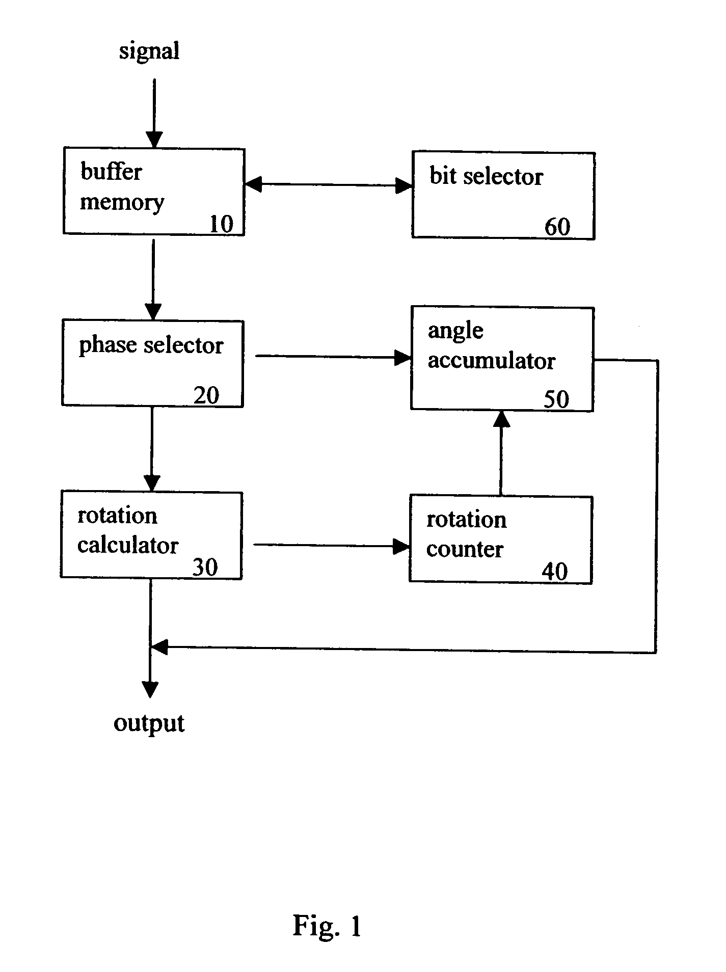
[0019]FIG. 1 illustrates the system diagram of the CORDIC circuit of this invention. As shown in this figure, the CORDIC circuit of this invention comprises a buffer memory 10 to record a plurality or a plurality of group of coordinate values; a phase selector 20 to determine a rotation direction according to values recorded in said buffer memory; a rotation calculator 30 to rotate an input coordinate for a predetermined angle and to calculate resulting coordinate value after such rotation; a rotation counter 40 to count number of rotation being made to said input coordinate; and an angle accumulator 50 to accumulate total rotation angle being made to said input coordinate according to value recorded by said rotation counter. The CORDIC circuit of this invention may further comprise a bit selector 60 to shift bits of said input coordinate.

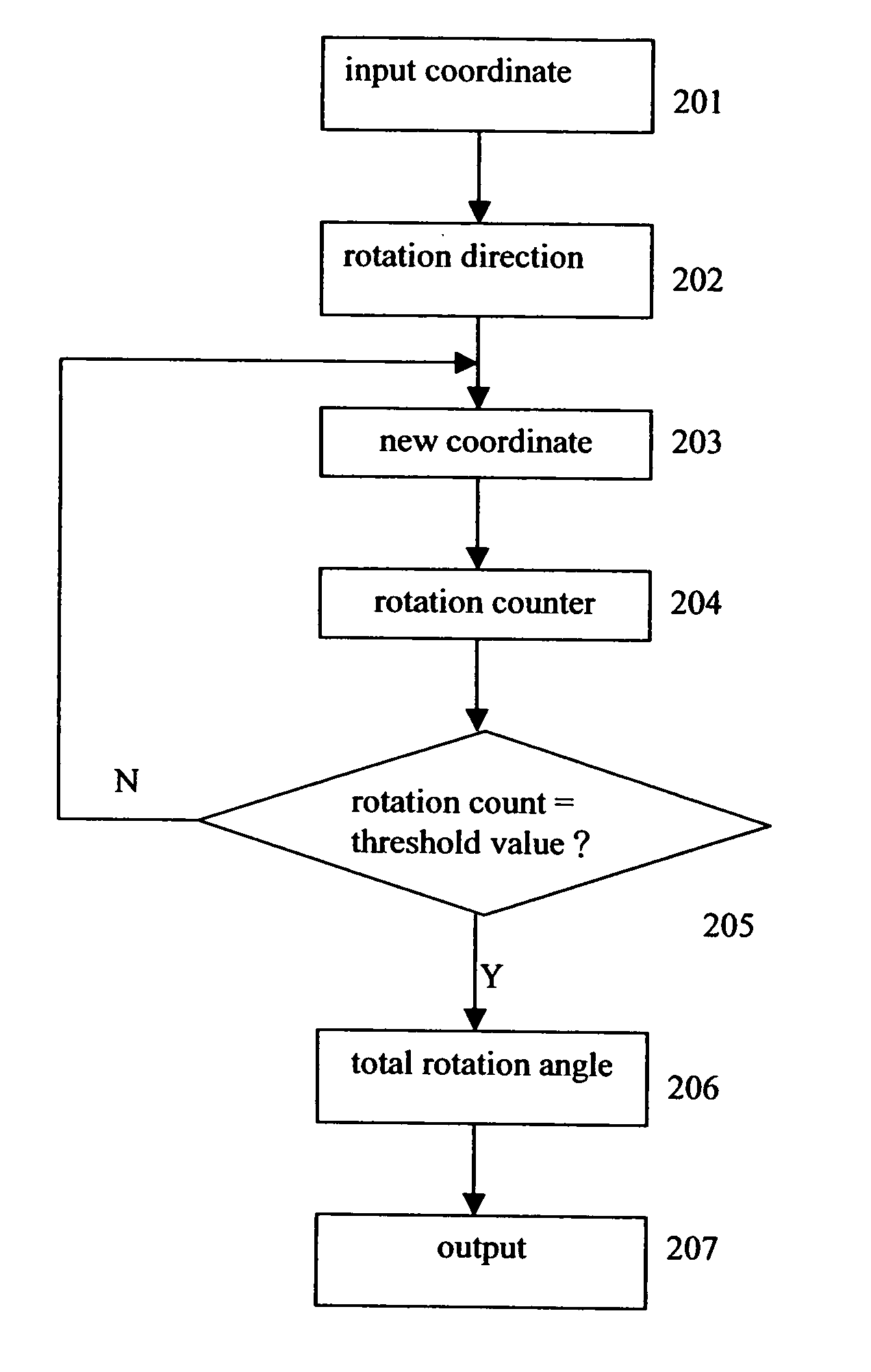
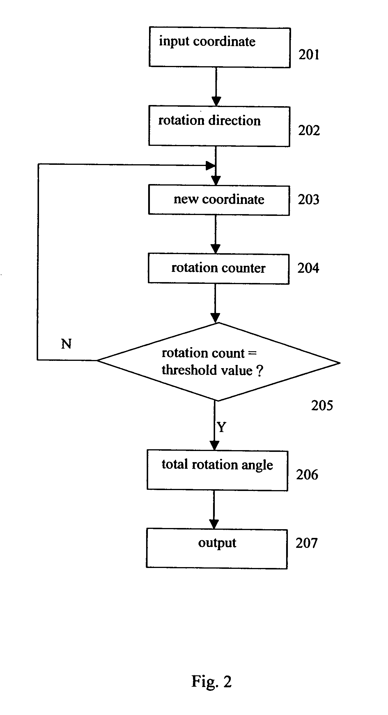
[0020] The calculation of the CORDIC circuit of this invention will be described in the following. FIG. 2 shows the flowchart of calculation of t...


PUM


Abstract

The CORDIC circuit of this invention comprises a buffer memory to record a plurality or a plurality of group of coordinate values; a phase selector to determine a rotation direction according to values recorded in said buffer memory; a rotation calculator to rotate an input coordinate for a predetermined angle and to calculate resulting coordinate value after such rotation; a rotation counter to count number of rotation being made to said input coordinate; and an angle accumulator to accumulate total rotation angle being made to said input coordinate according to value recorded by said rotation counter. The CORDIC circuit of this invention may further comprise a bit selector to shift bits of said input coordinate.

Description

FIELD OF THE INVENTION [0001] The present invention relates to a novel CORDIC circuit, especially to a simplified CORDIC circuit. The present invention provides a simplified structure for the CORDIC circuit to reduce gate count of the CORDIC circuit. BACKGROUND OF THE INVENTION [0002] Among all kinds of signal processing circuits, the CORDIC (coordinate rotation digital computer) circuit is a very useful tool to rotate the positive real number of the coordinate (rectangular coordinate or polar coordinate) representing a sampled signal. The CORDIC calculation is often used in the integration of digital signals. For example, when a CORDIC vector rotation processor receives a digital signal, it may conduct CORDIC processing of the digital signal by referring to the rotation angle of a reference signal, to generate a shifting signal. After such a processing, the sampling phase or sampling frequency of the signal processor may be modified, such that quality of digital signal processing m...

Claims


Application Information

Patent Timeline
Patent Type & Authority Applications(United States)
IPC IPC(8): G06F7/544G06F15/00
CPCG06T3/60G06F7/5446
Inventor WEN, KUEI-ANNPENG, CHIA-SHENGCHUANG, YUAN-SHIN
Owner KUEI ANN WEN
Learn More