Standing frame with lift, support and transport of user

a technology of user-supported frame and standing frame, which is applied in the field of portable standing frame with electromechanical lifting means, can solve the problems of complex and even mechanized apparatus, inability to allow the patient's pants to be removed, and many devices currently available to assist with patient transfer without adequate power assist featur

Inactive Publication Date: 2005-10-06
BARATTIA EDWARD C
View PDF6 Cites 22 Cited by
  • Summary
  • Abstract
  • Description
  • Claims
  • Application Information

AI Technical Summary

Benefits of technology

[0010] The invention provides a standing frame that gives an opportunity for a person without an ability to stand without assistance (but with some amount of upper body strength and control) to be raised to a standing position, moved a short distance, and then seated at the nearby location. The base of the apparatus supports a removable vertical rail assembly. The base also holds a battery and charger to operate a power winch. The vertical part of the device supports a cushioned knee support and a power driven winch that feeds out and takes in rope through a pulley system. The rope is attached to a heavy-duty belt that is placed as low as possible on the backside of a seated person. As the winch takes in rope the knees of the seated person are pressed into the cushioned knee support and the pull of the winch then raises the person to an upright standing position. The entire apparatus, along with the standing individual, can be rotated or moved laterally a short distance.

Problems solved by technology

Such devices range from simple rail structures to more complex and even mechanized apparatus.
Many of the devices currently available to assist with patient transfer do not have an adequate power assist feature.
Those that do are not capable of allowing the patient's pants to be removed to allow for using the toilet or to dress or undress.

Method used


Image

  • Standing frame with lift, support and transport of user
  • Standing frame with lift, support and transport of user
  • Standing frame with lift, support and transport of user

Examples


example 1

[0034] Recently, my father lost his ability to walk. He was able to stand himself upright by holding on to grab bars mounted to walls.

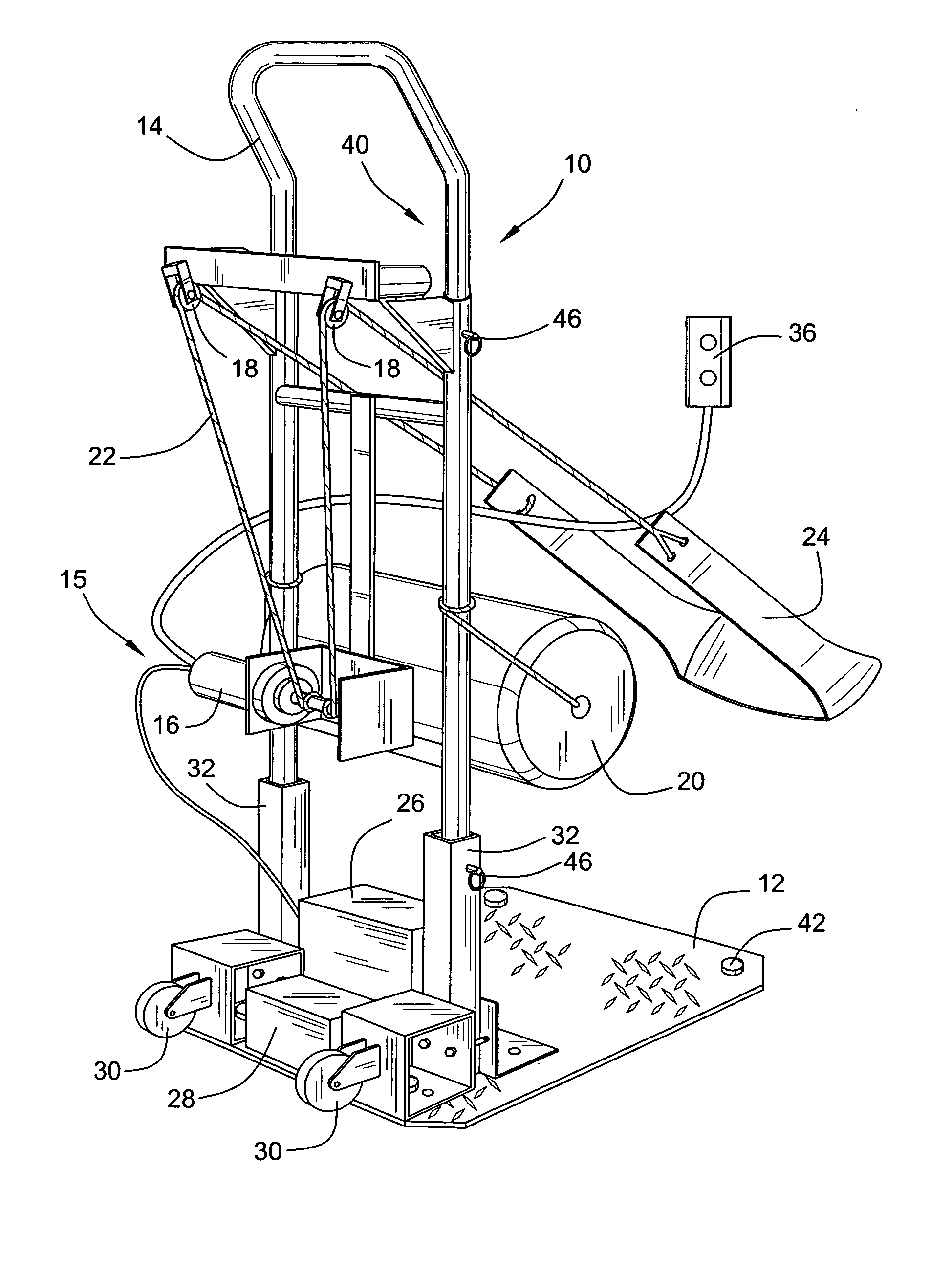
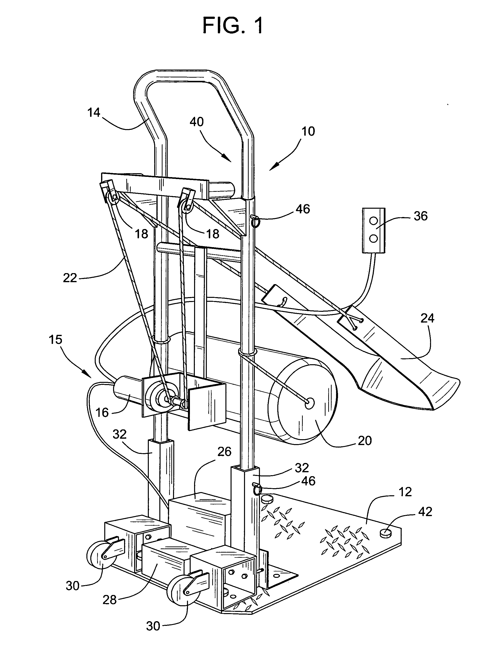
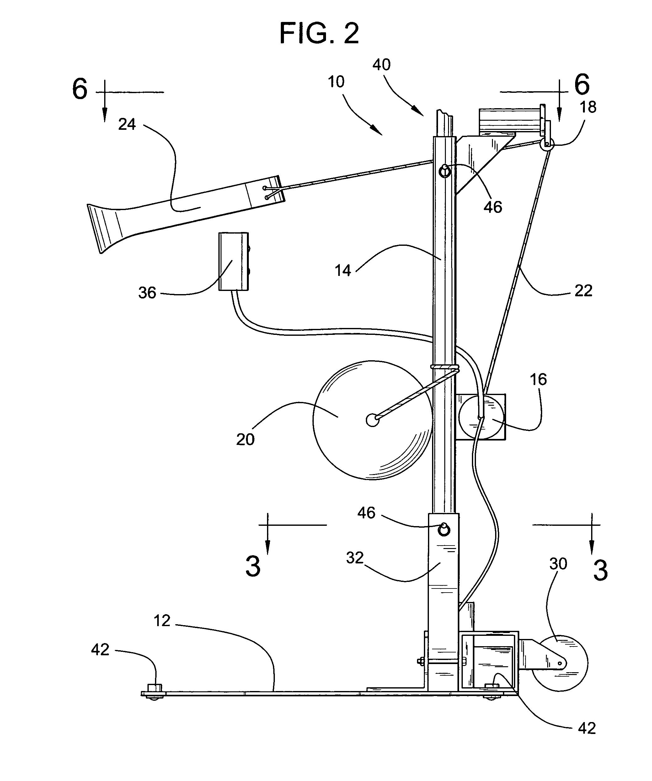
[0035] It was not always possible to have a grab bar in front of him to allow him to stand. For those situations I modified a two-wheel hand truck (dolly) by fastening a larger floor plate that he could stand on while pulling himself into a standing position. Months later he was unable to maintain a standing position because his knees would buckle. I made a further modification to the hand truck that placed a padded bar in front of his knees to prevent his knees from buckling.

[0036] Within 3 months, he was unable to pull himself into a standing position without substantial assistance from a helper to lift him with a gait belt while he tried to stand. This became too difficult for the helper or care giver, so I made another modification to the hand truck by placing a 12 volt D.C. winch with a rope and pulley system attached to a heavy belt. With the ...


PUM


Abstract

A standing frame to aid a person with inability to stand or walk to rise to a standing position and transfer from or to other locations such as chairs, toilets, beds. The standing frame has a flat rigid base with fixtures mounted to it that support a vertical rail frame. The vertical rail frame may be adjusted vertically and the frame incorporates a winch and pulley system that uses rope and a belt to lift a person to a standing position and lower the person to a sitting position. The vertical frame also provides handholds for the person being raised to steady himself. The base is preferably provided with roller balls to easily reposition the frame with a person aboard for relocating the person.

Description

RELATED APPLICATIONS [0001] This application claims the benefit of U.S. Provisional Application Ser. No. 60 / 558,034, filed Mar. 31, 2004, and herein incorporated by reference.FIELD OF THE INVENTION [0002] This invention relates in general to structures, systems, and procedures for the lifting, transfer, and transport of individuals requiring assistance and more particularly to a portable standing frame with electromechanical lifting means associated with an inexpensive, yet dependable, safe and easy way to operate with or without assistance and enables a person to be lifted, supported and transported to and from a sitting position. BACKGROUND OF THE INVENTION [0003] Over the years past many standing-frames have been devised to assist a wheel chair bound or bed ridden person to stand. Such devices range from simple rail structures to more complex and even mechanized apparatus. Examples of the range of such prior art devices may be seen by reference to the following U.S. patents: Pat...

Claims


Application Information

Patent Timeline
Patent Type & Authority Applications(United States)
IPC IPC(8): A61G5/14A61G7/10
CPCA61G7/1015A61G7/1046A61G7/1051A61G2200/36A61G7/1094A61G7/1096A61G2200/34A61G7/1074
Inventor BARATTIA, EDWARD C.
Owner BARATTIA EDWARD C
Why Eureka
Try Eureka