
Computer cooling system

a cooling system and computer technology, applied in ventilation systems, electrical equipment casings/cabinets/drawers, domestic cooling apparatus, etc., can solve the problems of unsatisfactory current cooling requirements, unsatisfactory prior art methods of controlling a fan to cool a processor, and one aspect of fan control that has been continuously neglected, so as to reduce the noise of the fan and the effect of improving the control of the fan speed

Inactive Publication Date: 2005-10-06
AOPEN
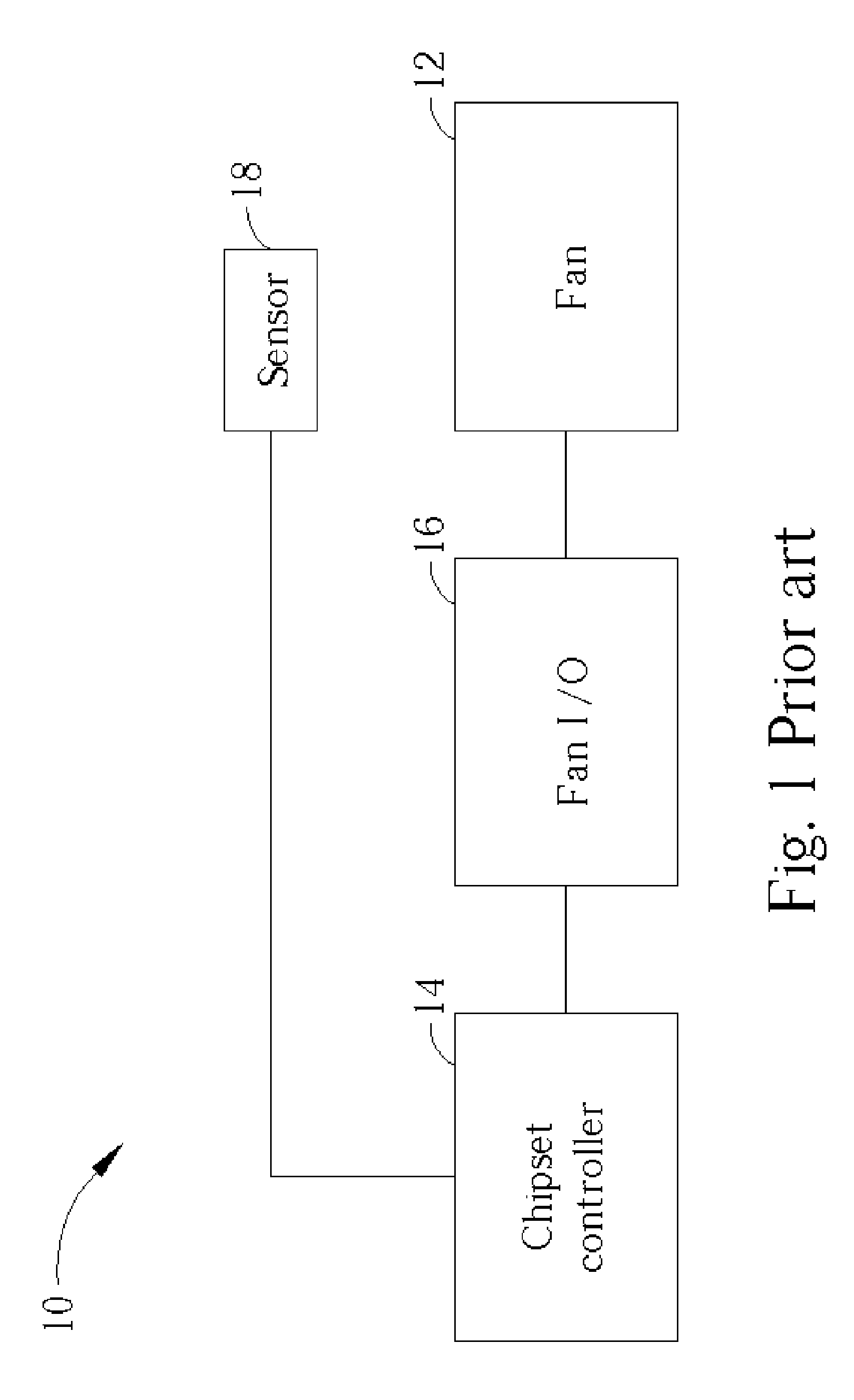
View PDF15 Cites 37 Cited by
  • Summary
  • Abstract
  • Description
  • Claims
  • Application Information

AI Technical Summary

Benefits of technology

[0009] It is therefore a primary objective of the claimed invention to provide a cooling system for a computer that minimizes fan noise level while improving cooling performance and power conservation.
[0011] According to the claimed invention, the method can further increase the fan power by a first power when the vital temperature increases by a first temperature, and decrease the fan power by a second power when the vital temperature decreases by a second temperature. The first power is directly proportional to the first temperature, and the second power is directly proportional to the second temperature.
[0014] It is an advantage of the claimed invention that the differential consideration of temperature, that is, the measurement of the change in vital temperature, improves the control of the fan speed.
[0015] It is a further advantage of the claimed invention that the differential consideration of temperature and the corresponding differential setting of the fan speed result in reduction in fan speed, and thus, fan noise and power consumption.

Problems solved by technology

One aspect of fan control has been continuously neglected in development of control schemes and related circuitry, that is, fan noise level.
The prior art methods of controlling a fan to cool a processor cannot suitably meet current cooling requirements.
Having been developed for performance and power savings, these methods typically suffer in other areas of concern.
Specifically, noise levels can be uncomfortably high in conventional fan cooling applications.

Method used


Image

  • Computer cooling system
  • Computer cooling system
  • Computer cooling system

Examples


Embodiment Construction

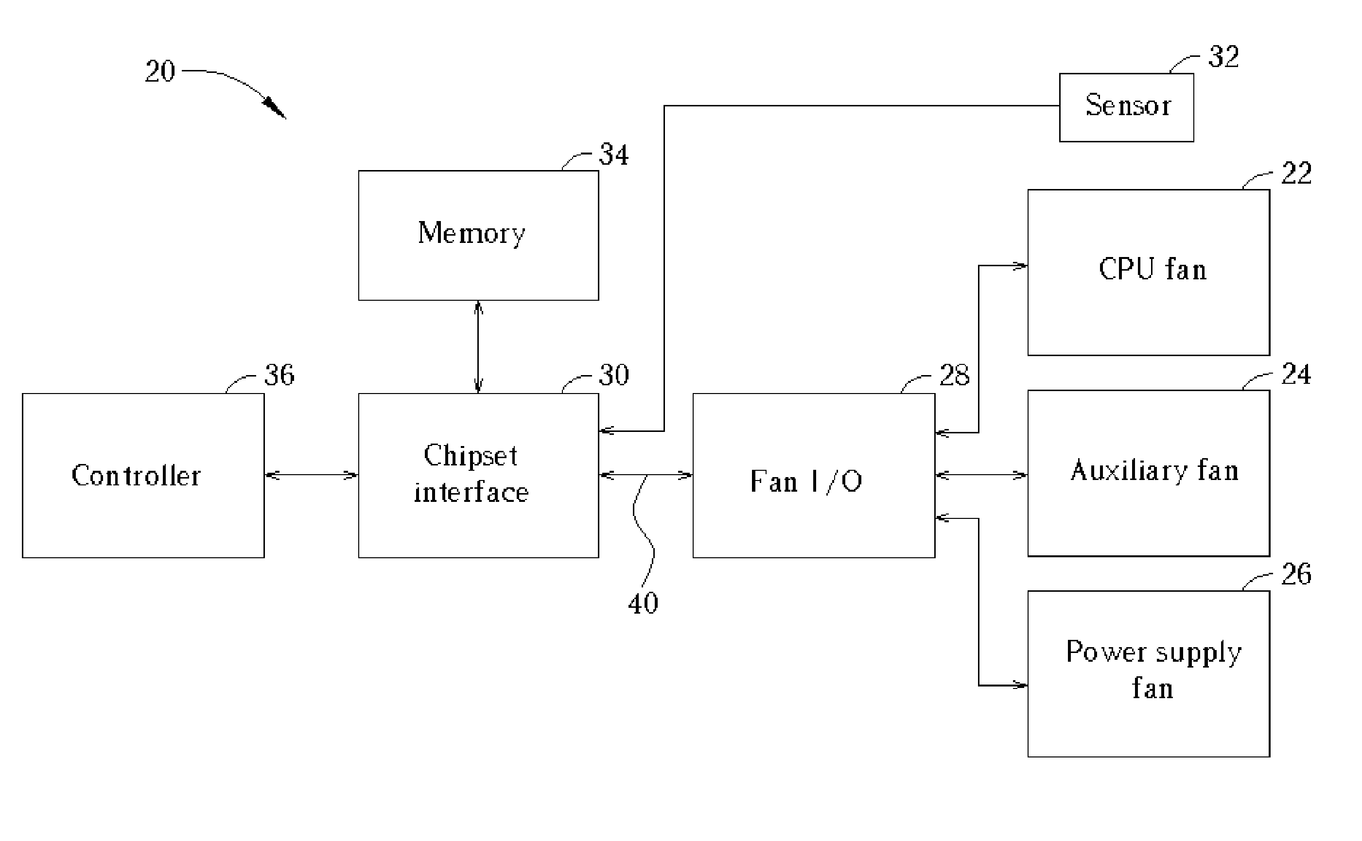
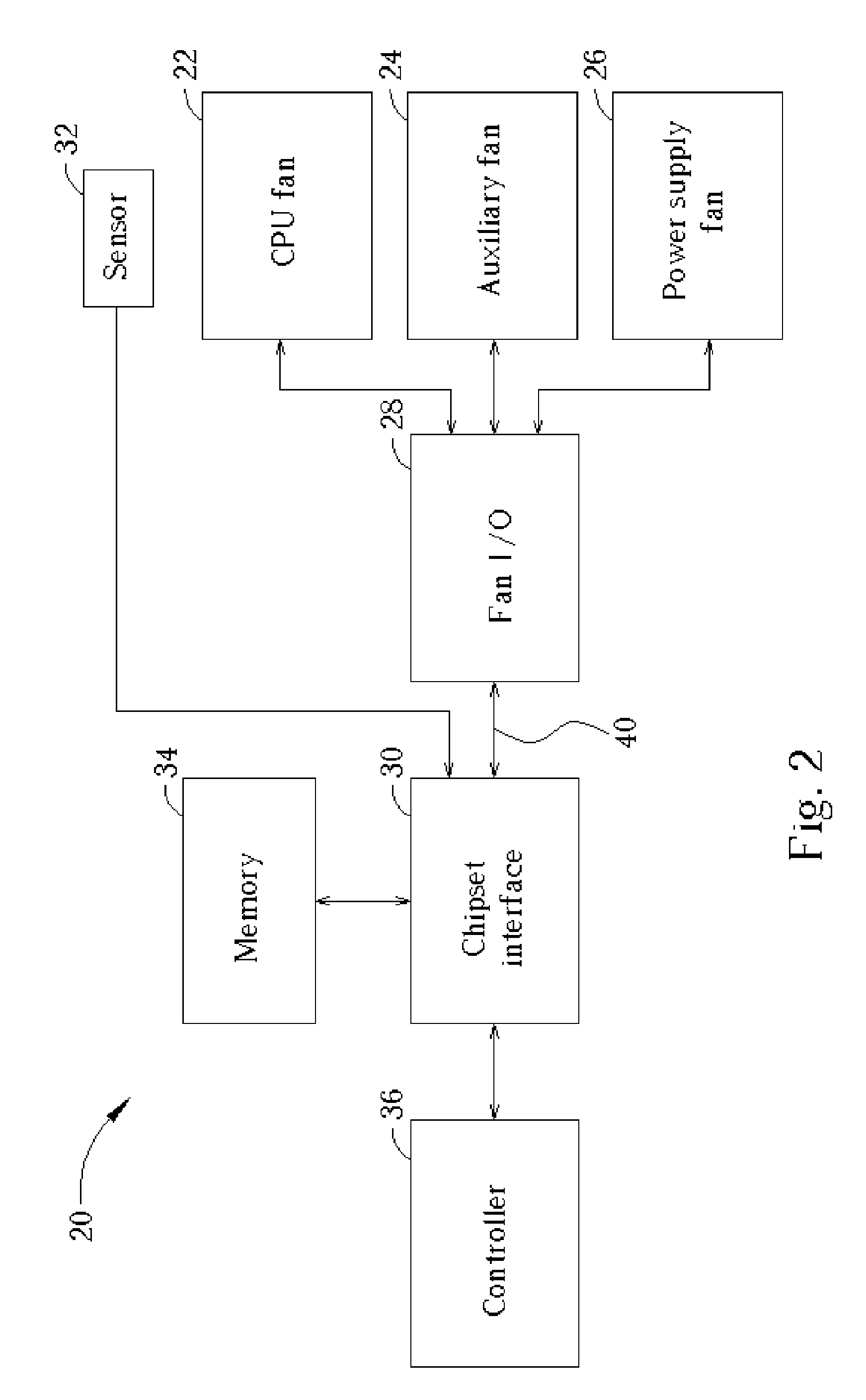
[0023] Please refer to FIG. 2 showing architecture of a cooling system 20 for a computer according to the present invention. The cooling system 20 includes a series of fans, of which all are optional as long as one is provided, including a CPU fan 22, an auxiliary (case) fan 24, and a power supply fan 26 installed in the computer. The fans 22, 24, 26 are three pin fans, the pins being power and ground pins for operation, and a tachometer output pin for rotational speed measurement. The CPU fan 22 is attached to a CPU heat sink, the auxiliary fan 24 is typically mounted inside the computer case near vent holes, and the power supply fan 26 is provided in the AC to DC power supply enclosure. The cooling system 20 can be applied in a wide variety of computer designs each having different fan arrangements. It is anticipated that many such implementations will include only the CPU fan 22, which is the most common active cooling device for modern processors. The cooling system further incl...


PUM


Abstract

A cooling system includes a cooling fan, a fan input-output module for transmitting a control signal to the fan for controlling the rotational speed of the fan, and a chipset interface for generating the fan control signal based on a change in a vital temperature of the computer system. Further provided is a controller for receiving the vital temperature and forwarding the vital temperature to the chipset interface, and a temperature transducer for generating the vital temperature and outputting the vital temperature to the controller. The chipset interface monitors a rotational speed of the cooling fan, and monitors a vital temperature of the computer system. The chipset interface then sets the fan power based on a change in the vital temperature. When the vital temperature decreases, the fan power is reduced to slow the fan, and when the vital temperature increases, the fan power is increased to speed the fan.

Description

CROSS REFERENCE TO RELATED APPLICATIONS [0001] This application is a continuation of application Ser. No. 10 / 601,783, filed Jun. 24, 2003.BACKGROUND OF THE INVENTION [0002] 1. Field of the Invention [0003] The present invention relates to a cooling system for a computer, and more specifically, to a fan speed controlling cooling system for a personal computer. [0004] 2. Description of the Prior Art [0005] As computer processing speeds steadily increase, the need for high capacity cooling systems becomes essential. Proper cooling prevents heat related failure of the processor when under operating loads. Typical cooling systems have progressed beyond the venerable constantly running fan to include temperature sensors and related control circuits for dynamically adjusting fan speed. While several fan speed control schemes have been developed, nearly all focus entirely on maximizing cooling effects or reducing power consumption. One aspect of fan control has been continuously neglected i...

Claims


Application Information

Patent Timeline
Patent Type & Authority Applications(United States)
IPC IPC(8): F24F7/00F25B21/02F25D17/04F25D23/12G06F1/20H05K5/00H05K7/20
CPCG06F1/206Y10S236/09Y02B60/1275H05K7/20209Y02D10/00
Inventor CHENG, YU-CHIHZHENG, LINHO, WEI-CHUANYAO, JIN-WANGCHANG, TING-YU
Owner AOPEN
Learn More