Method and apparatus for patterning of bore surfaces

Active Publication Date: 2005-10-06
MAKINO MILLING MASCH CO LTD
View PDF46 Cites 15 Cited by
  • Summary
  • Abstract
  • Description
  • Claims
  • Application Information

AI Technical Summary

Problems solved by technology

This process may produce shear stress in the cylinder wall by tearing or cutting the metal, resulting in metal being pushed over the graphite particles in the cast iron.
Engine blow-by may occur when the air/fuel mixture leaks past the piston rings, into the crankcase, possibly blowing the mixture into the air cleaner.
Oil blow-by may occur when oil enters the combustion chamber past the piston rings, oftentimes ending up in the burnt exhaust.
Oil blow-by can be a major emission problem.
This may al

Method used


Image

  • Method and apparatus for patterning of bore surfaces
  • Method and apparatus for patterning of bore surfaces
  • Method and apparatus for patterning of bore surfaces

Examples


Embodiment Construction

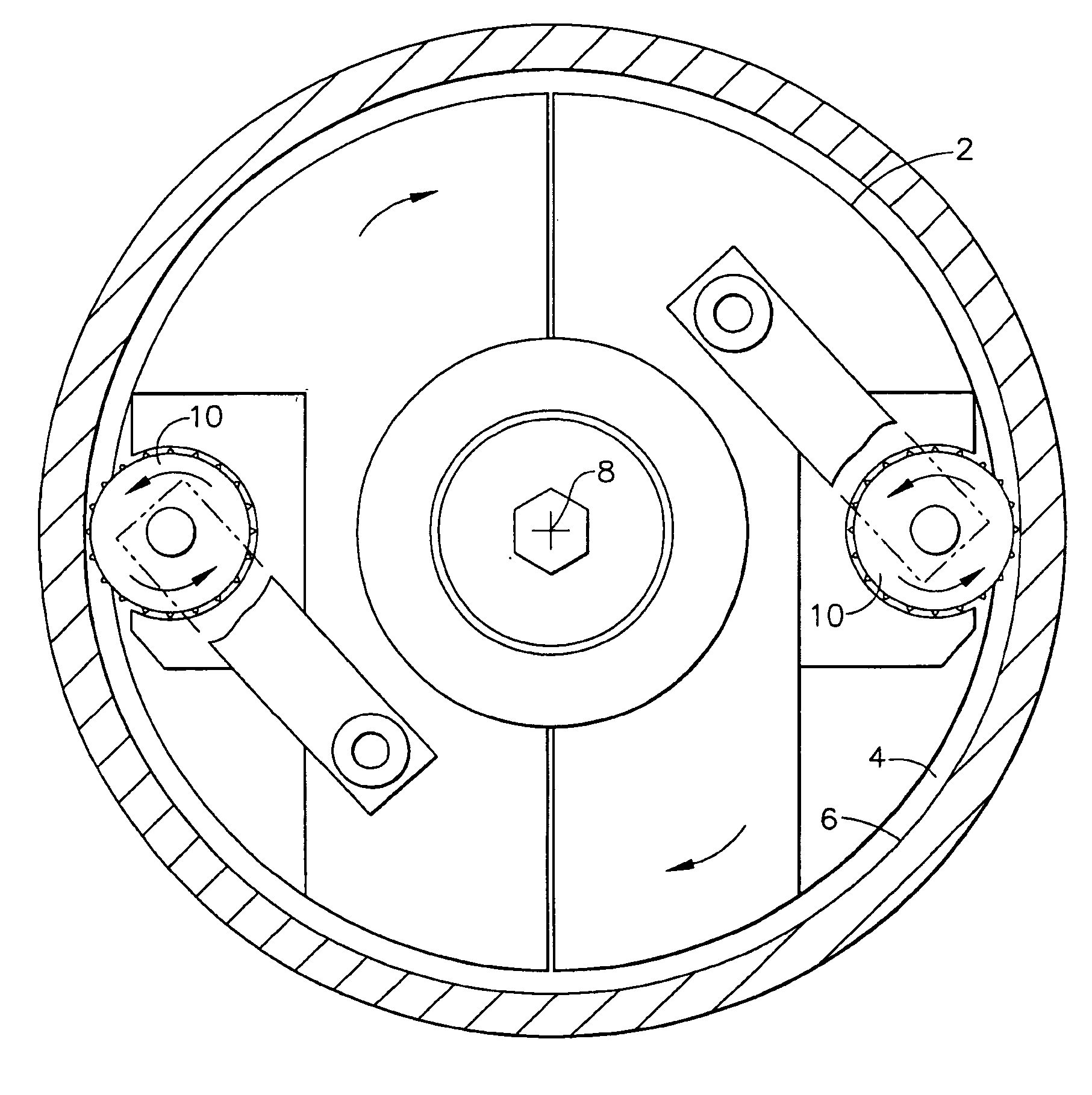
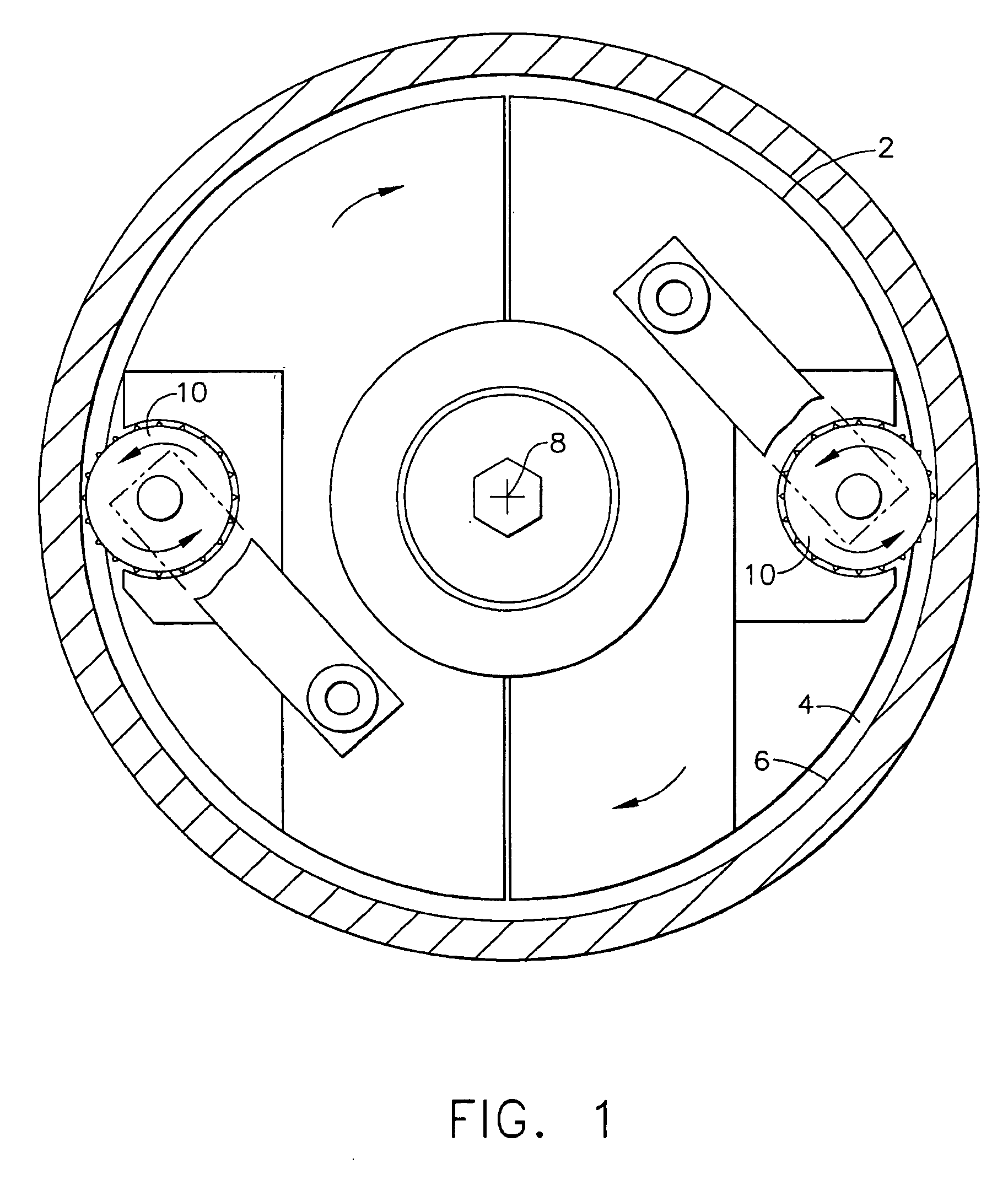
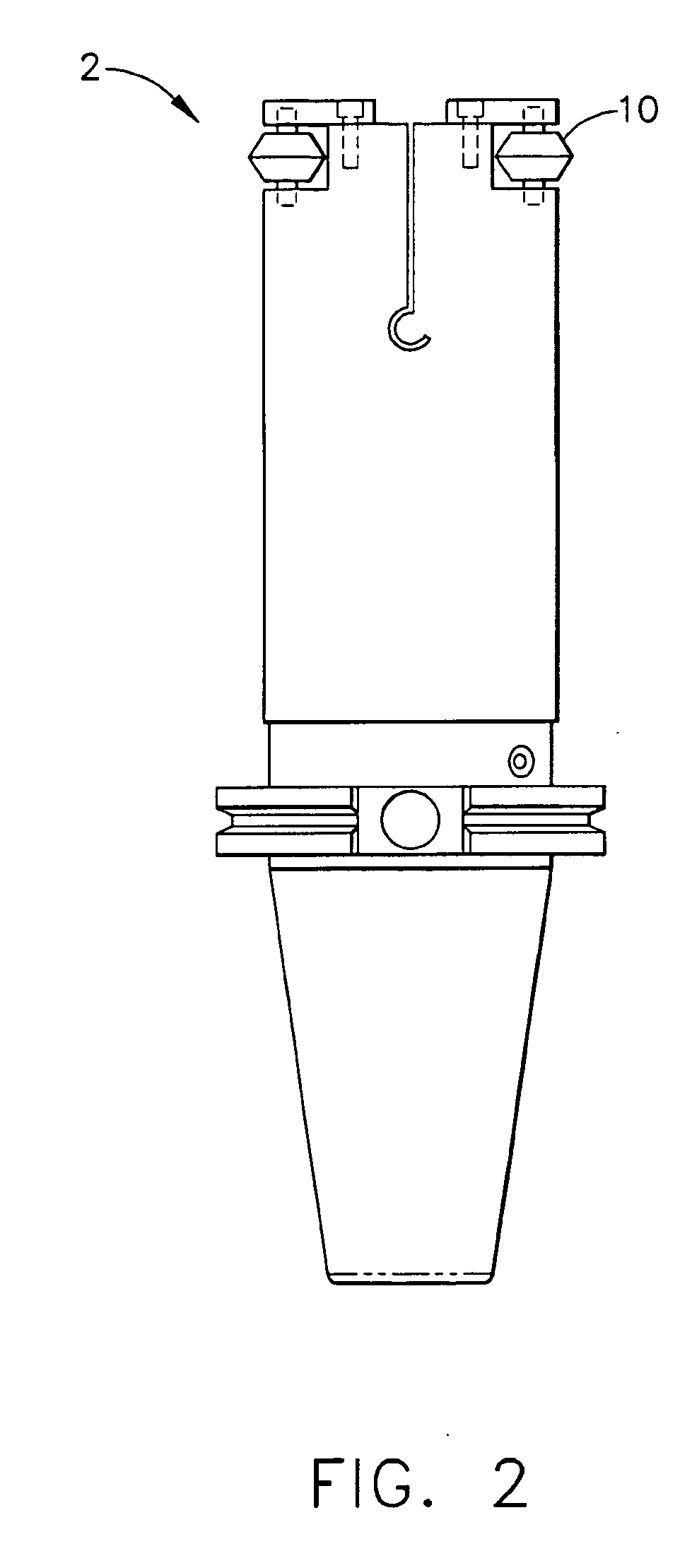
[0018] Referring now to the drawings in detail, wherein like numerals indicate the same elements throughout the views, FIGS. 1-4 show tool 2 comprising a plurality of rollers 10 located proximate to its circumference. While two rollers 10 are shown in these figures, it will be appreciated that any number of rollers 10 may be used based on various considerations that will be apparent to those of ordinary skill in the art. Each roller 10 may have its own axis, or as shown in FIG. 4 by way of example only, a roller 20 may share an axis with another roller 10. Tool 2 is configured to rotate and advance axially into cylinder bore 4, and may be mounted to any suitable device or devices operable to accomplish such rotation and axial advancement. Tool axis 8, about which tool 2 rotates, may be aligned parallel to cylinder bore 4 axis when tool 2 is advanced into cylinder bore 4. Alternatively, tool axis 8 may have other appropriate orientation as will be apparent to those of ordinary skill ...


PUM

PropertyMeasurementUnit
Perimeteraaaaaaaaaa
Compressive stressaaaaaaaaaa

Abstract

An apparatus comprises a rotating member having one or more rollers. The one or more rollers have a plurality of protuberances. The rollers may be advanced toward a surface during rotation of the rotating member, such as toward a bore surface. The protuberances are configured to make a pattern of discrete indentations in the surface upon engagement of the protuberances with the surface. The apparatus is particularly suited for creating oil-retention pockets in the surface of an engine cylinder and other uses. The apparatus may be used to create a pattern of oil-retention pockets or other pockets in a cylinder with varying pocket density in a single pass.

Description

PRIORITY [0001] This application claims priority from the disclosure of U.S. Provisional Patent Application Ser. No. 60 / 549,583, entitled “Method and Apparatus for Patterning of Bore Surfaces,” filed Mar. 3, 2004. This application also claims priority from the disclosure of U.S. Provisional Patent Application Ser. No. 60 / 644,732, entitled “Tool with Selectively-Biased Member,” filed Jan. 18, 2005, which is incorporated by reference herein.BACKGROUND OF THE INVENTION [0002] The present invention relates generally to the formation of pockets in surfaces. More specifically, it is directed to the formation of discrete oil retention pockets in the walls of engine cylinders. [0003] The diameter and surface finish of engine cylinder walls are important to engine operation, as such characteristics may affect friction between the cylinder and piston rings, ring wear, and blow-by. The process of manufacturing engine cylinders typically includes rough and finish boring operations, followed by ...

Claims


Application Information

Patent Timeline
IPC IPC(8): B21B19/08B21D9/08B21D15/06B23B27/24B23P9/02
CPCB21D15/06B23P9/02B23B2270/20B23B27/24
Inventor WEIDMER, STAN C.
Owner MAKINO MILLING MASCH CO LTD
Why Eureka
Try Eureka