Mounting structure for engine cover

a technology for mounting structures and engine covers, which is applied in the direction of machines/engines, mechanical actuated clutches, and combustion air/fuel air treatment, etc. it can solve the problems of difficult to set the gap between the cylinder head cover and the engine cover to a desired size, the position of fixing portions and the portions to be fixed cannot be confirmed, and the design properties are deteriorated. , to achieve the effect of superior design properties and easy implementation of mounting work

a technology for mounting structures and engine covers, which is applied in the direction of machines/engines, mechanical actuated clutches, and combustion air/fuel air treatment, etc. it can solve the problems of difficult to set the gap between the cylinder head cover and the engine cover to a desired size, the position of fixing portions and the portions to be fixed cannot be confirmed, and the design properties are deteriorated. , to achieve the effect of superior design properties and easy implementation of mounting work

US20050217634A1Inactive Publication Date: 2005-10-06TOYODA GOSEI CO LTD

Image

  • Mounting structure for engine cover
  • Mounting structure for engine cover
  • Mounting structure for engine cover

Examples


embodiment

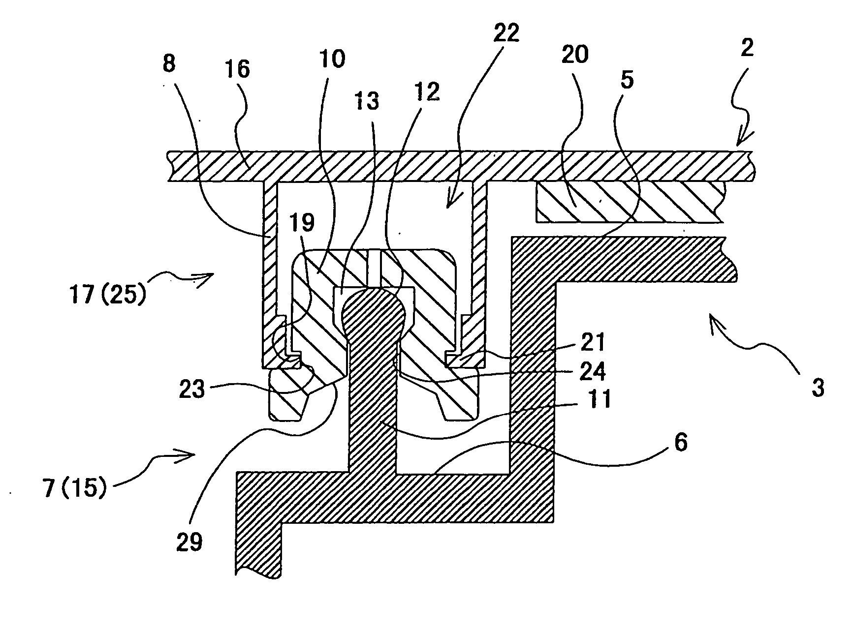
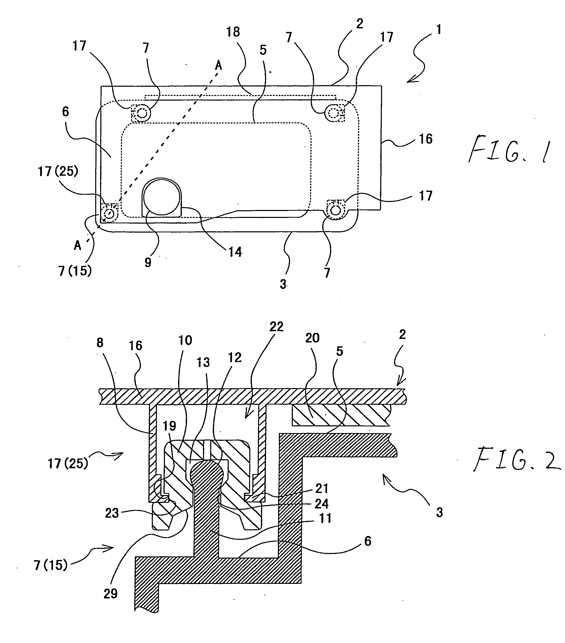
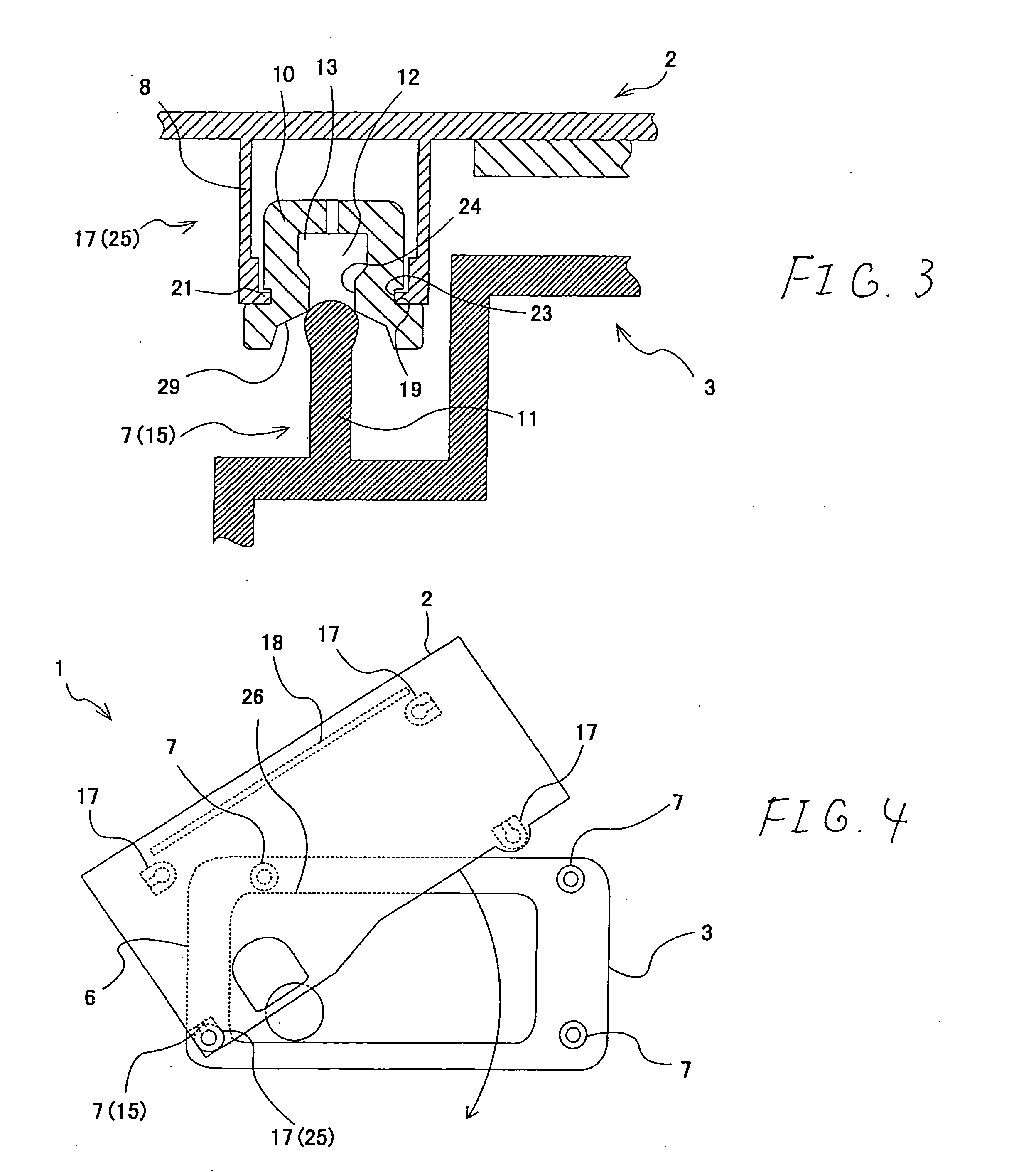
[0039] A plan view showing exemplarily an engine cover mounting structure according to the invention is shown in FIG. 1, and sectional views taken along the line A-A in FIG. 1 are shown in FIGS. 2 and 3. In addition, in the engine cover mounting structure according to the embodiment, a plan view showing exemplarily an appearance of an engine cover mounted to an engine member is shown in FIG. 4.

[0040] In the engine cover mounting structure 1 of the embodiment, an engine cover 2 is mounted to a cylinder head cover 3 as an engine member.

[0041] The cylinder head cover 3 is formed into a substantially box-like shape which is opened downwardly. A lower stepped portion 6, which is lowered one stage in height, is formed circumferentially along an outer edge of an upper bottom portion 5 of the cylinder head cover 3. A protruding portion to be fixed 7, which extends upwardly, is provided on the lower stepped portion 6 at a position which corresponds to each of four corners of the cylinder h...


PUM


Abstract

An engine cover mounting structure comprising an engine member and an engine cover, wherein a plurality of portions to be fixed to which fixing portions provided on the engine cover are mounted are provided so as to be situated below an upper surface of a cylinder head cover of the engine member. In addition, a positioning portion is provided on the engine cover. Then, in a state where a base fixing portion is mounted or temporarily mounted to a base portion to be fixed, while the other fixing portions are not mounted to the other portions to be fixed, when the engine cover revolves about the base fixing portion, so that the positioning portion is brought into abutment with a surface of the engine member, the fixing portions other than the base fixing portion are disposed at positions facing the portions to be fixed, respectively.

Description

[0001] This application is based on Japanese Patent Application No. 2004-102707, which is incorporated herein by reference. BACKGROUND OF THE INVENTION [0002] 1. Field of the Invention [0003] The present invention relates to a mounting structure for an engine cover which covers an engine. [0004] 2. Related Art [0005] In engine compartments of automobiles in recent years, it becomes a general practice to provide an engine cover above an engine. This engine cover has functions to shield noise that has leaked from the engine (transmitted noise) and to improve the design properties of the interior of the engine compartment by preventing the sight of the engine. [0006] The engine cover is generally mounted to the cylinder head cover of the engine. As this occurs, the engine cover is, in general, mounted to the cylinder head cover through a screw-fastening via bolts (see, for example, JP2001-98954A). Through holes are provided in the engine cover disclosed in JP2001-98954A, and threaded s...

Claims


Application Information

Patent Timeline
06 Oct 2005
Publication
US20050217634A1
IPC
F02B77/00; F01M11/04; F02B67/06; F02F7/00; F16D13/58
CPC
F02F7/006; F01M11/04
Inventors
NONOGAKI, HARUHIKO; MAEDA, ITSURO