
Disposable filter means for smoking

a filter and smoking technology, applied in the field of smoking and smoking devices, can solve the problems of lessening the enjoyment derived from smoking, frequent burnt areas immediately in communication with the exit portal of the burning chamber, and laborious cleaning of the pipes and cigarette holders, so as to facilitate heat exchange, reduce the temperature of smoke passing, and increase the amount of waste cooled

Inactive Publication Date: 2005-10-06
PIPARETTE
View PDF6 Cites 4 Cited by
  • Summary
  • Abstract
  • Description
  • Claims
  • Application Information

AI Technical Summary

Benefits of technology

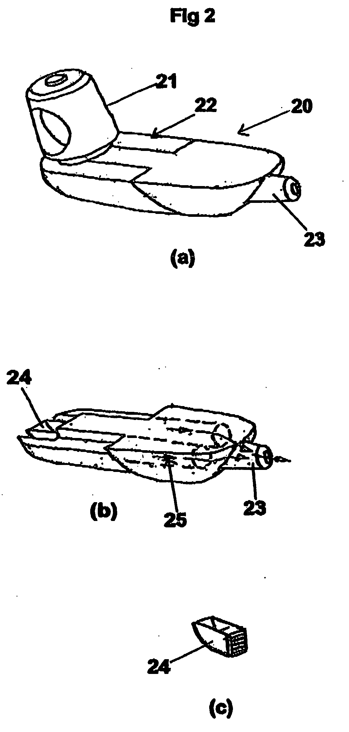
[0016] The receiving member is preferably made of temperature resistant materials to prevent the burning of the receiving member from high temperatures associated with the burning chamber and smoke and the production of embers from the burning product. In a preferred embodiment, the receiving member has an outer metal casing and an inner ceramic layer.
[0018] In one preferred embodiment the receiving member is shaped so that its outer surface facilitates heat exchange. In one preferred form the outer surface of the receiving member has one or more laterally extending fins. In one preferred form the outer surface of the receiving member is elongate and may include laterally extending fins. The ability to lower the temperature of smoke passing through the receiving member increases the amount of waste cooled to solid or liquid form that may be trapped by the receiving member.
[0028] The receiving member is preferably shaped to resist burning from the high temperatures and embers generated from the burning product. The receiving member is preferably made of temperature resistant materials to prevent the burning of the receiving member from high temperatures associated with the burning chamber and smoke and the production of embers from the burning product. In a preferred embodiment, the receiving member has an outer metal casing and an inner ceramic layer. In a preferred embodiment the receiving member has a passage that allows smoke to enter at or adjacent to one end of the receiving member and exit adjacent another end of the receiving member.
[0030] In one preferred form the receiving member is shaped so that its outer surface facilitates heat exchange. In one preferred embodiment the outer surface of the receiving member has one or more laterally extending fins. In one preferred form the outer surface of the receiving member is elongate and may include laterally extending fins. The ability to lower the temperature of smoke passing through the receiving member increases the amount of waste cooled to solid or liquid form that may be trapped by the receiving member.

Problems solved by technology

With time, the waste byproducts clog the pipe preventing smoke from passing through the internal passage.
The cleaning of pipes and cigarette holders is a laborious task repeated on a regular basis.
Furthermore, the cleaning of pipes and cigarette holders usually leaves some waste thereby contaminating subsequent smoke passing through the stem and lessening the enjoyment derived from smoking.
In addition, the area immediately in communication with the exit portal of the burning chamber is often burnt as a consequence of the high temperature of the smoke reducing the ability of the area to filter the smoke.
Eventually the pipe or holder must be replaced because of the damaged area adjacent the burning chamber.
These problems are an ongoing source of frustration to smokers as effective filtering of the smoke is reduced.
Where filtering is reduced over a period of time, the smoker's health can be adversely affected.
As well, the regular ongoing requirement to clean the pipes and holders before a person can enjoy having a smoke often turns the person away from using such smoking devices.

Method used


Image

  • Disposable filter means for smoking
  • Disposable filter means for smoking
  • Disposable filter means for smoking

Examples


Embodiment Construction

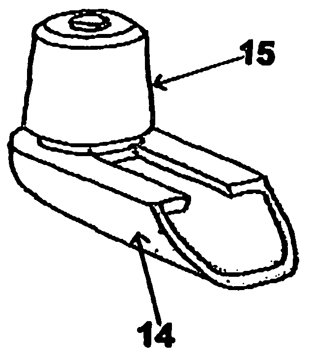
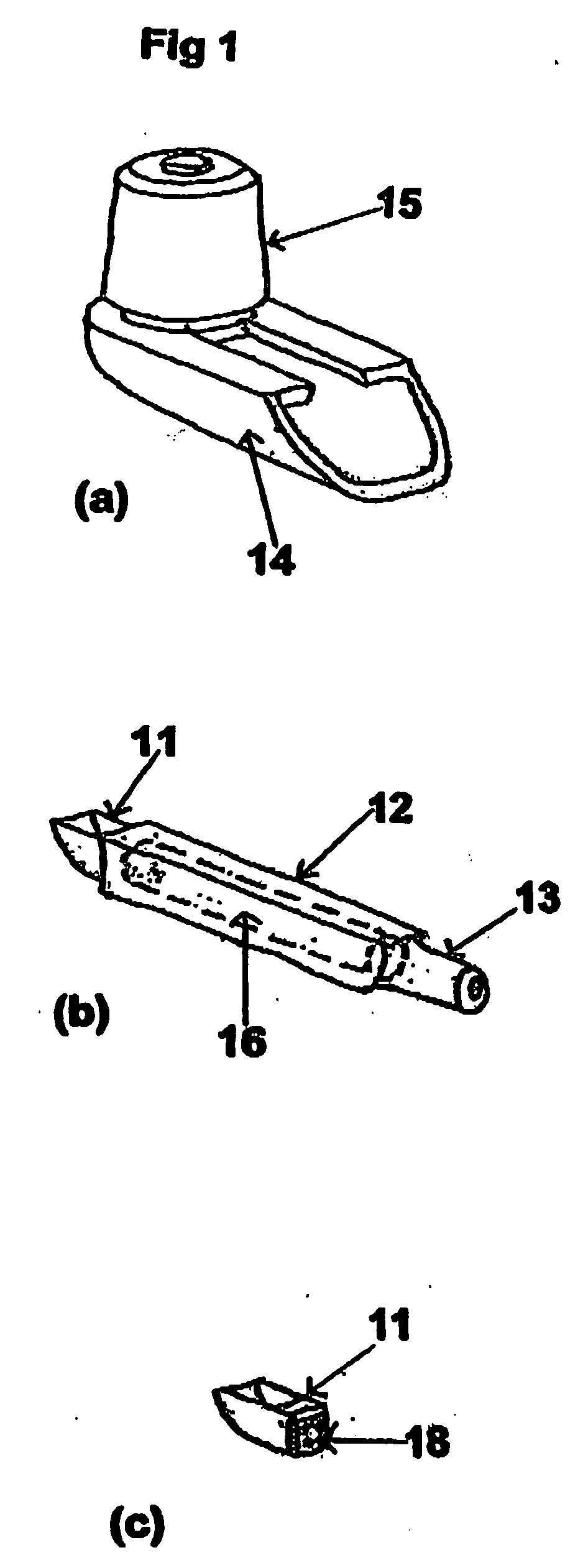
[0059] With reference to FIG. 1, there is shown an unassembled smoking device comprising a receiving member in the form of a shank trap 11, a filter housing 12 with a mouth piece 13, stem 14 and bowl 15. The shank trap 11 is attachable to the filter housing 12 at the opposing end to the mouth piece 13. The filter housing 12 has an acetate paper filter 16 (shown in phantom) locatable within the housing 12. The filter housing 12 with the shank trap 11, when assembled forms a filter assembly locatable within stem 14. The bowl 15 is locatable on the stem 14. When assembled, the burning chamber of the bowl 15 is in communication with the shank trap 11 and the filter housing 12. Smoke from the burning chamber passes into the shank trap 11 as the smoker draws on the mouthpiece 13, the smoke then passes through the paper acetate filter 16 within the filter housing 12 and is inhaled by the smoker. The shank trap 11 is shaped to collect moisture, tar and other end products while allowing smok...


PUM


Abstract

The present invention is directed to a disposable shank trap for use with a pipe to filter smoke from the burning chamber. The shank trap can include or be associated with other filters to further filter smoke. The advantage of the shank trap is that it can be easily replaced, avoid problems with the cleaning of the pipe, provide efficient filtering of the smoke and efficient usage of the tobacco.

Description

[0001] This application is a continuation-in-part of a U.S. national phase application (application No. Unknown), which is based on PCT / AU02 / 01554, filed Nov. 15, 2002.FIELD OF INVENTION [0002] The present invention relates to smoking and smoking devices. The present invention has particular but not exclusive application to disposable accessories and parts for pipe and cigarette holders. BACKGROUND OF THE INVENTION [0003] When smoking tobacco from either a pipe, cigarette holder or cigarette, the smoke includes nicotine, moisture, tar and other burnt tobacco byproducts. The pipe and holder usually includes a filter in the stem to limit the amount of burnt byproducts being inhaled by the smoker. With the pipe and holder, the elongate stem also assists in limiting the amount of burnt byproducts reaching the smoker, because the smoke loses heat and the suspended waste changes from a gaseous phase to a solid or liquid phase and consequently is trapped by the filter. [0004] With time, th...

Claims


Application Information

Patent Timeline
Patent Type & Authority Applications(United States)
IPC IPC(8): A24F1/02A24F1/20A24F13/00
CPCA24F1/20A24F1/02
Inventor KOLLASCH, STEFANTEYS, BRAD
Owner PIPARETTE
Learn More