Exhaust heat recovery system

Inactive Publication Date: 2005-10-06
DENSO CORP
View PDF3 Cites 98 Cited by
  • Summary
  • Abstract
  • Description
  • Claims
  • Application Information

AI Technical Summary

Benefits of technology

[0007] The present invention was made in view of the problem inherent in the conventional techniques and an object thereof is to provide an e

Problems solved by technology

One of main factors which reduce the energy efficiency ratio is that a large quantity of thermal energy is carried away together with exhaust gases.
However, the energy recovery efficiency ratio of the exhaust heat re

Method used


Image

  • Exhaust heat recovery system
  • Exhaust heat recovery system
  • Exhaust heat recovery system

Examples


Example

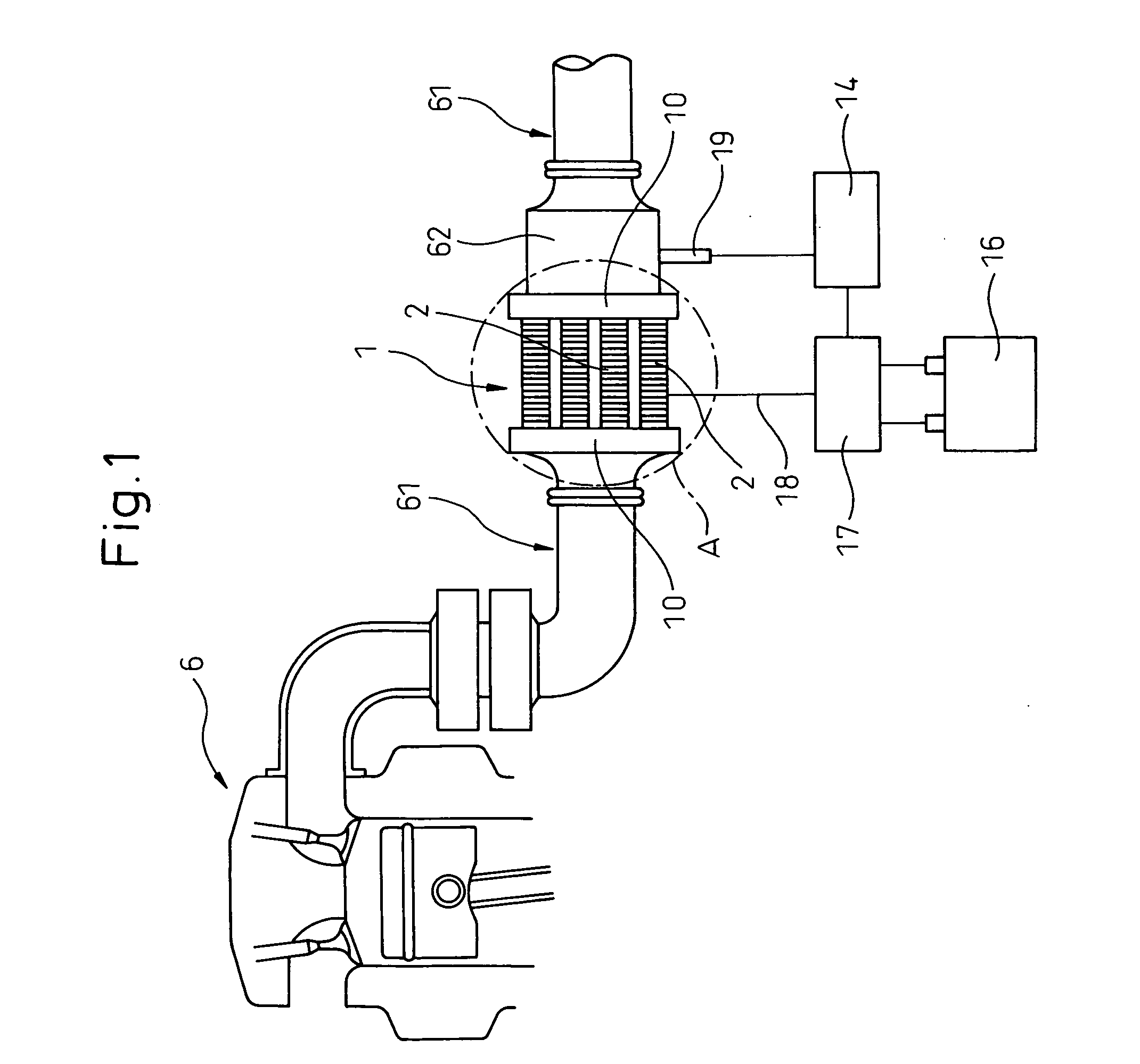
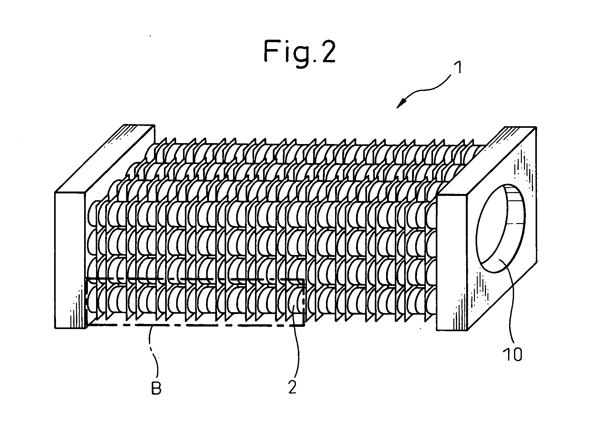
[0048] An exhaust heat recovery system according to a first embodiment of the invention will be described with reference to FIGS. 1 to 11.

[0049] As shown in FIGS. 1 and 2, the exhaust heat recovery system according to the embodiment has an exhaust path 10 which allows the passage of exhaust gases of an internal combustion engine 6 and thermoelectric modules 2 which are disposed in the exhaust path 10.

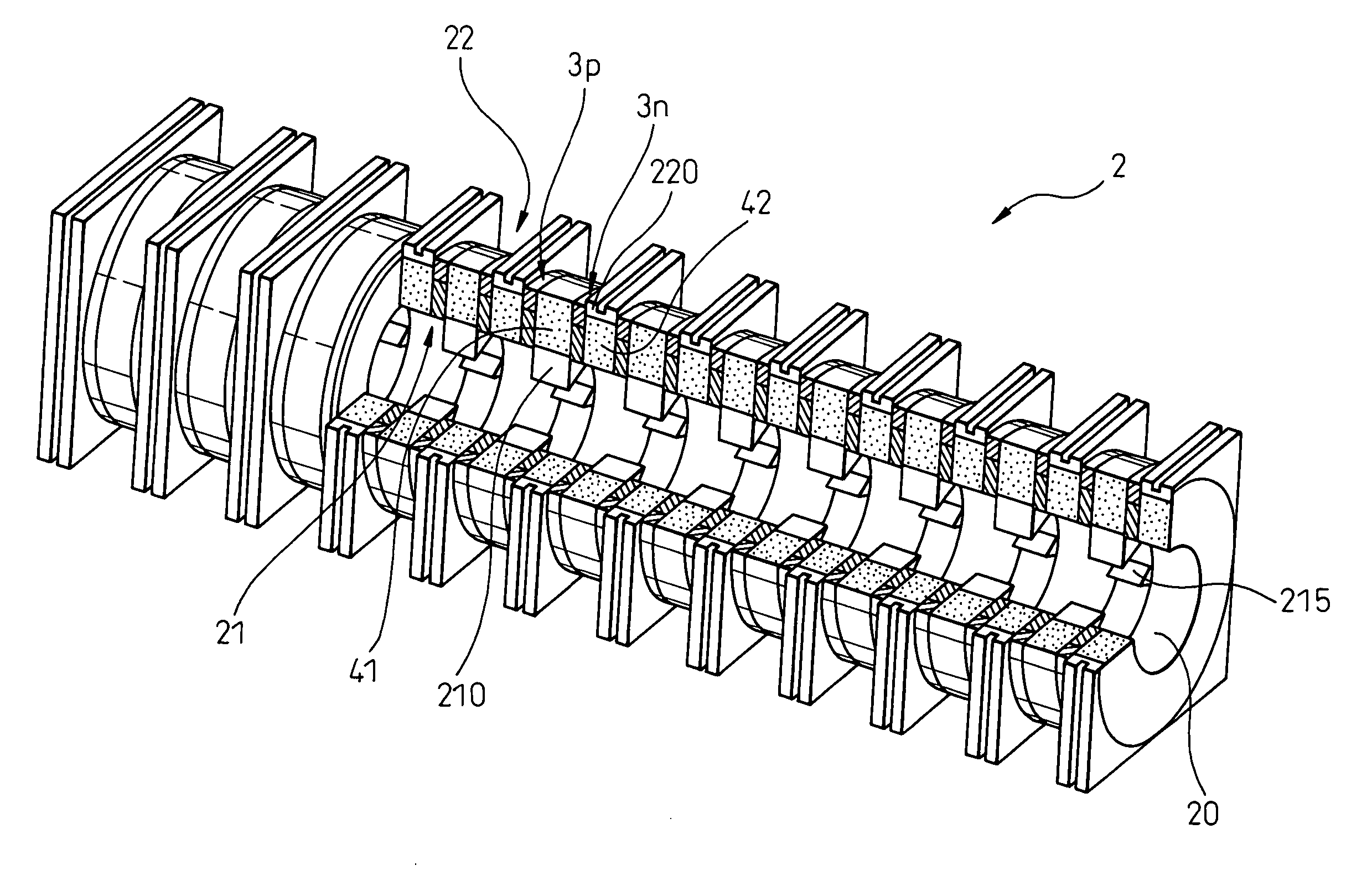
[0050] The thermoelectric module 2, as shown in FIGS. 3 and 4, has an exhaust pipe portion 20 which allows the passage of exhaust gases therethrough, p-type semiconductors 3p and n-type semiconductors 3n which both constitute thermoelements 3 which each convert a difference in temperature between a high temperature end portion 21 and a low temperature end portion 22 into electricity, low temperature side heat exchanging portions 220 disposed at the low temperature side end portions 22 of the thermoelectric module 2, and high temperature side heat exchanging portions 210 disposed at th...

Example

Second Embodiment

[0084] A second embodiment is such that the fabrication process of the thermoelectric module 2 is modified based on the exhaust heat recovery system according to the first embodiment. The contents of the second embodiment will be described using FIGS. 6, 7, 12 and 13.

[0085] In this embodiment, as shown in FIG. 12, respective semiconductors 31p, 32p (31n, 32n) having substantially annular flat plate-like shapes were prepared in advance, and a semiconductor 3p (3n) shown in FIG. 13 was obtained by combining the respective semiconductors so prepared. Thereafter, respective heat insulating support members 41, 42 and the semiconductors 3p, 3n were stacked together to thereby obtain a thermoelectric module.

[0086] Here, as to the respective semiconductors 31p, 32p, 31n, 32n, desired shapes may be obtained directly by virtue of calcination or desired shapes can be realized by machining calcined products. In addition, as shown in FIG. 13, in combining the semiconductor 31...

Example

Third Embodiment

[0090] A third embodiment is such that the configuration of separated thermoelements is modified based on the exhaust heat recovery system according to the first embodiment. The contents of the third embodiment will be described using FIGS. 14 and 15.

[0091] In a thermoelectric module 2 according to this embodiment, as shown at a portion (A) in FIG. 14 and in FIG. 15, a ratio (A / B) of the radial thickness A (FIG. 15) of high temperature elements 31p, 31n which are separated thermoelements of a high temperature side end portion 21 and the radial thickness B (FIG. 15) of low temperature elements 32p, 32n which are separated thermoelements of a low temperature side end portion 22 is made to change according to location in a longitudinal direction of an exhaust pipe portion 20.

[0092] Namely, as shown at a portion (B) in FIG. 14, the temperature T of exhaust gases changes depending on positions along the longitudinal direction of the exhaust pipe portion 20 and is highe...


PUM


Abstract

A thermoelectric module 2 constituting an exhaust heat recovery system has p-type semiconductors 3p and n-type semiconductors 3n which both constitute thermoelements 3 for converting a difference in temperature between high temperature side end portions 21 and low temperature side end portions 22 into electricity. The thermoelectric module 2 is constructed such that the n-type semiconductors 3n and the p-type semiconductors 3p are stacked alternately along a longitudinal direction of an exhaust pipe portion 20 with heat insulating support portions 41, 42 being interposed therebetween, and the n-type semiconductors 3n and the p-type semiconductors 3p are electrically connected to each other via electrode members at the high temperature side end portions 21 and the low temperature side end portions 22.

Description

BACKGROUND OF THE INVENTION [0001] 1. Field of the Invention [0002] The present invention relates to an exhaust heat recovery system that is disposed in an exhaust path, of an internal combustion engine in an automobile, to recover the exhaust heat carried by exhaust gases. [0003] 2. Description of the Related Art [0004] The energy efficiency of an automobile equipped with, for example, a gasoline engine is low and on the order of 15 to 20%. One of main factors which reduce the energy efficiency ratio is that a large quantity of thermal energy is carried away together with exhaust gases. To cope with this, conventionally, techniques have been proposed to enhance the total energy efficiency ratio by aggressively using the exhaust heat carried by the exhaust gases (for example, refer to Japanese Unexamined Patent Publication No. 2000-286469). [0005] In the conventional technique, there is disclosed an exhaust heat recovery system in which thermoelements which can convert a difference ...

Claims


Application Information

Patent Timeline
IPC IPC(8): F01N5/02F02G5/02F01N5/00F25B21/02H01L35/00H01L35/16H01L35/18H01L35/28H01L35/30H01L35/32
CPCF01N5/025F01N2240/04F02G5/02Y02T10/166H01L35/32Y02T10/16H01L35/00Y02T10/12H10N10/00H10N10/17
Inventor NISHIJIMA, YOSHIAKIAKIMOTO, KATSUHIDENOMURA, YURIOSASAKI, TATSUYOSHITSUKAMOTO, KEIJISAKAI, TSUTOMU
Owner DENSO CORP
Why Eureka
Try Eureka