
Mtf testing apparatus

a technology of testing apparatus and exhaust heat, which is applied in the direction of optical apparatus testing, television system, instruments, etc., can solve the problems of deteriorating measurement accuracy and inevitably producing exhaust heat in cameras, and achieves efficient exhaust heat dissipation, efficient exhaust heat, and greater contact area

Pending Publication Date: 2022-03-31
TRIOPTICS GMBH
View PDF11 Cites 0 Cited by
  • Summary
  • Abstract
  • Description
  • Claims
  • Application Information

AI Technical Summary

Benefits of technology

The patent describes an apparatus for testing the performance of an image sensor. The apparatus uses multiple cameras to capture images of a device under test, which can then be analyzed to determine its quality. The purpose of the apparatus is to provide better serviceability and improved accuracy in evaluating image quality.

Problems solved by technology

The cameras inevitably produce exhaust heat.
Thermal convection airflow can cause flicker in the captured images and may therefore deteriorate the accuracy of the measurement.

Method used


Image

  • Mtf testing apparatus
  • Mtf testing apparatus
  • Mtf testing apparatus

Examples


Embodiment Construction

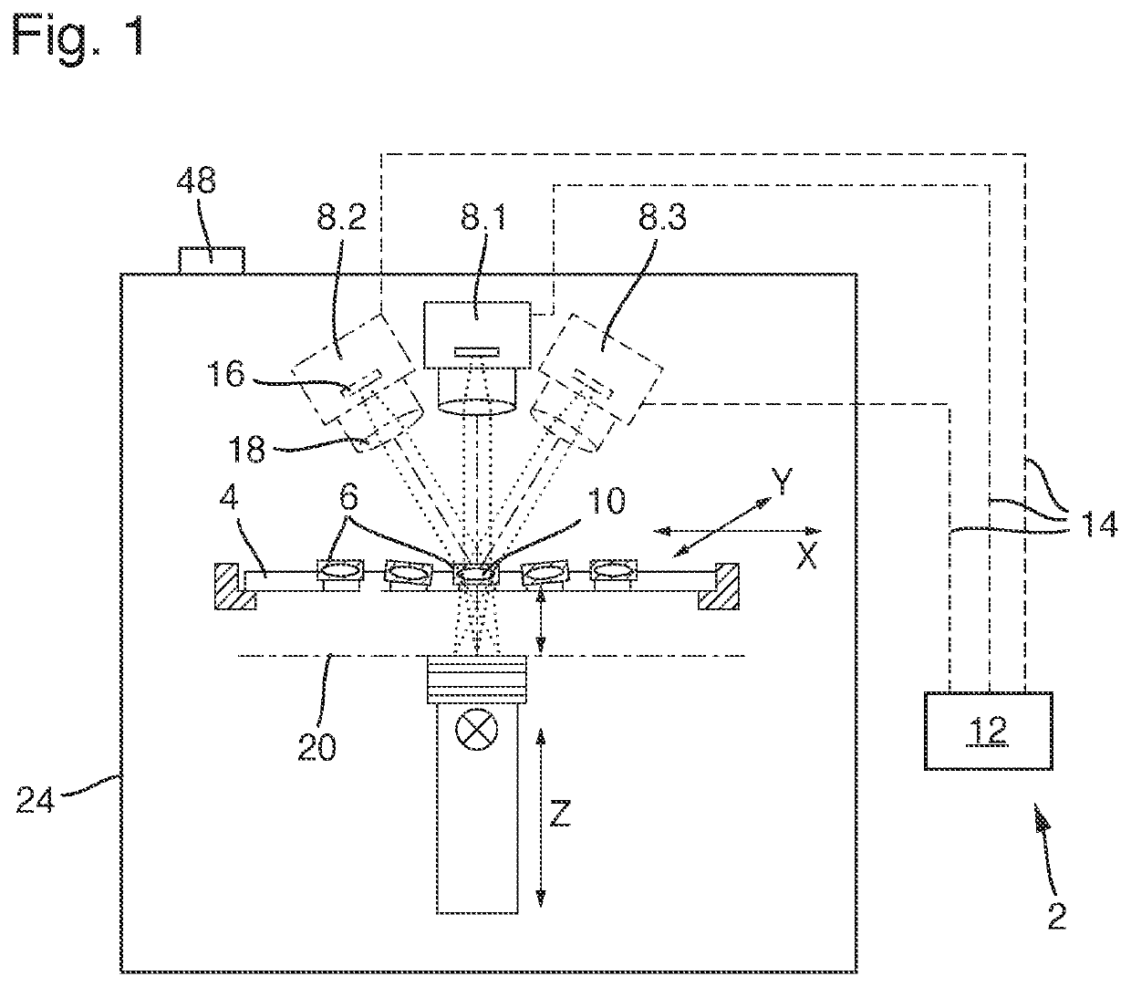
[0049]FIG. 1 is a schematic diagram illustrating a measurement principle of an MTF testing apparatus 2 according to an embodiment. The MTF testing apparatus 2 comprises a sample stage 4 for receiving a plurality of devices under test 6. For the sake of clarity of the drawings, only one device under test 6 is given a reference number. The sample stage 4 is a high quality tray for receiving the devices under test 6. The sample stage 4 is configured to avoid unwanted tilting of the samples, as it is indicated for two of the samples by way of an example. For the sake of clarity, the tilting angles are overemphasized.

[0050]The sample stage 4 is configured to perform a translational movement in an x-y-plane, which is illustrated by the crossed direction arrows. The movement of the sample stage 4 places one device under test 6 at a time at a position for testing. The sample stage 4 changes position to another device 6 to be tested after the MTF test for the first device under test 6 is fin...


PUM


Abstract

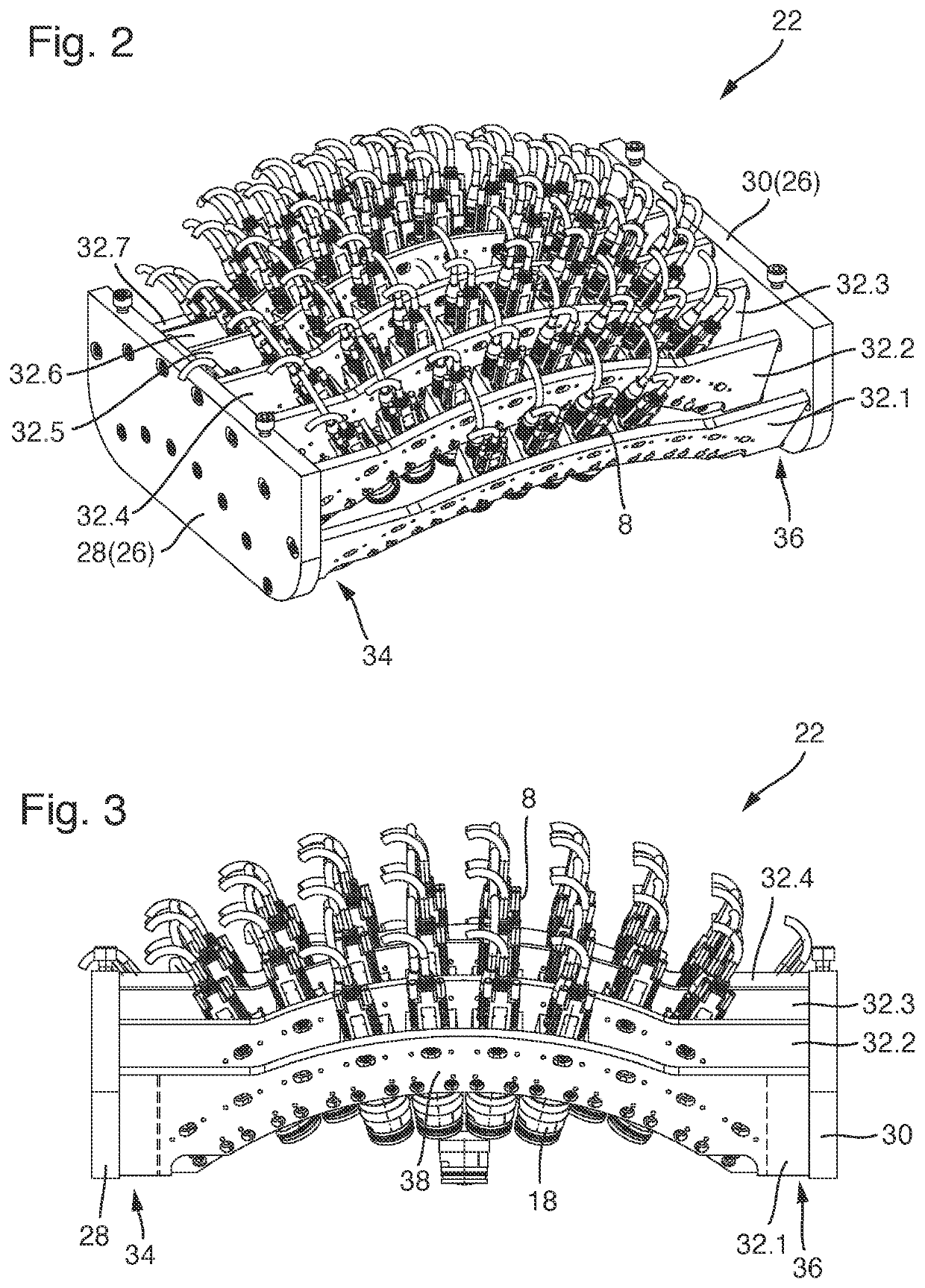
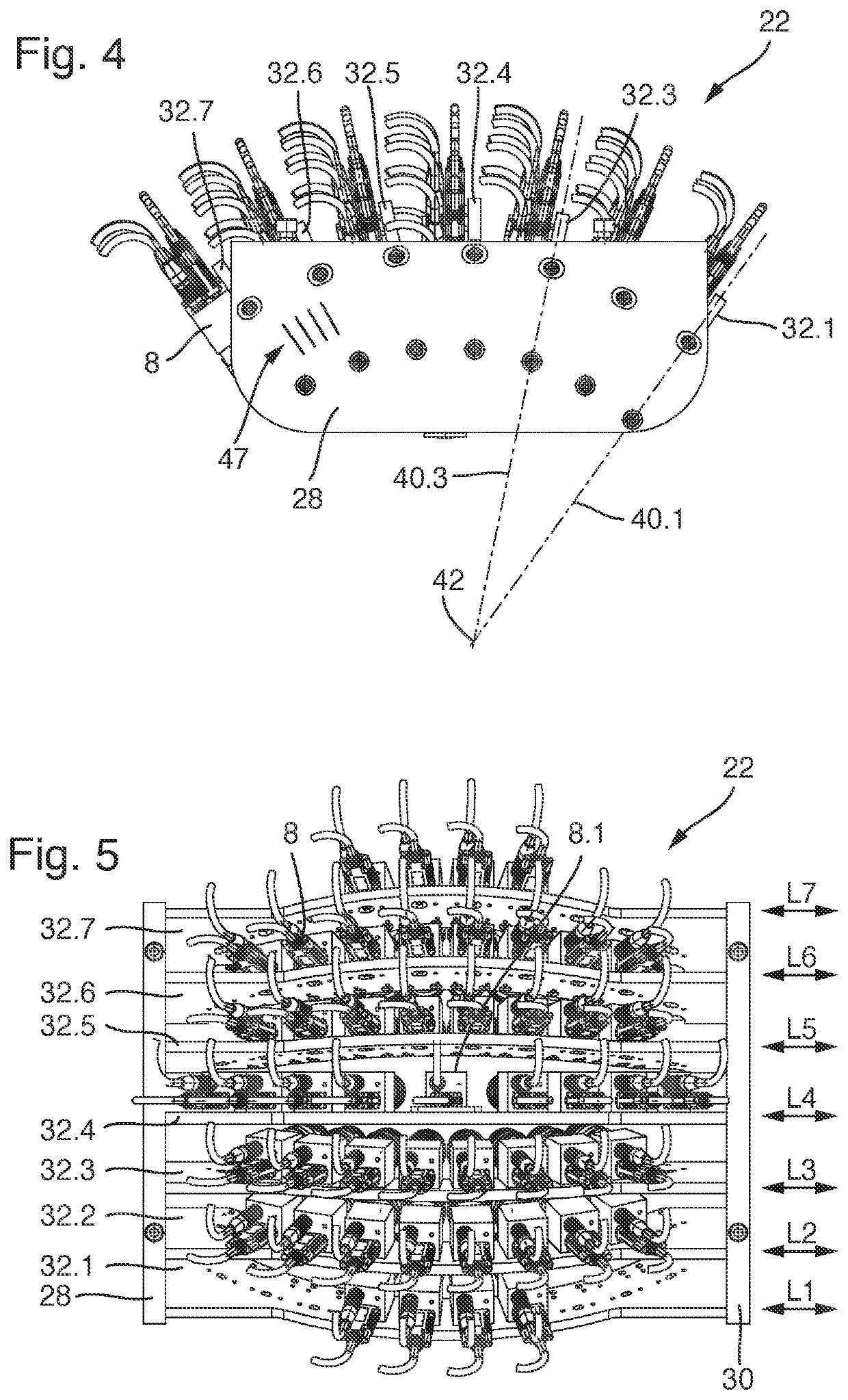
An MTF testing apparatus including a plurality of telescopic cameras each mounted at a fixed predetermined position on a camera holder, each camera receiving an image projected by at least one lens of a single device under test. A processor is coupled to the telescopic cameras. is the processor configured to receive image data from every telescopic camera and perform a plurality of MTF measurements, the telescopic cameras are mounted on the camera holder such that every telescopic camera captures image data resulting in an MTF measurement at a different field position of the lens. The camera holder comprises a holding structure and at least two brackets elongated elements projecting between first and second end portions, the end portions being releasably mounted on the holding structure, and at least two cameras are mounted on every bracket and the brackets are individually detachable from the holding structure.

Description

CROSS-REFERENCE TO RELATED APPLICATION[0001]The present application claims the benefit of priority to DE 10 2020 125 064.9 filed on Sep. 25, 2020, the entire contents of each of which is incorporated herein by reference.BACKGROUNDField[0002]The present disclosure relates to testing apparatus and more particularly to an MTF testing apparatus, comprising: a sample stage for receiving at least one device under test, the device under test comprising at least one lens, a plurality of telescopic cameras which are each mounted at a fixed predetermined position on a camera holder which is a rigid structure in that the telescopic cameras receive an image projected by the at least one lens of a single device under test, and a processor coupled to the telescopic cameras via at least one data link, wherein the telescopic cameras are configured to send image data via the data link to the processor and the processor is configured to receive image data from every telescopic camera and to perform a...

Claims


Application Information

Patent Timeline
Patent Type & Authority Applications(United States)
IPC IPC(8): G01M11/02H04N5/247H04N5/225G03B17/56H04N23/90
CPCG01M11/0292H04N5/247G01M11/0214G03B17/561H04N5/22521G01M11/0207G01M11/0257H04N23/52H04N23/90
Inventor POIKAT, RALF
Owner TRIOPTICS GMBH
Learn More