
Preform assembly, container assembly, and method of manufacture

Inactive Publication Date: 2005-10-06
GRAHAM PACKAGING PET TECH
View PDF7 Cites 16 Cited by
  • Summary
  • Abstract
  • Description
  • Claims
  • Application Information

AI Technical Summary

Benefits of technology

[0022] With one or more of the embodiments described above, the present invention provides a number of advantages. The present invention facilitates production of preform assemblies and container assemblies wherein a finish ring is composed of a material different from that of a preform or container to which the finish ring is radially interengaged. Likewise, the present invention facilitates application of finish rings of various sizes and / or materials, to a common size preform and / or container. Moreover, the present invention enables a decrease in the cycle time required to produce a preform because the constraint of the process—forming the neck finish portion—can be subordinated to a separate, parallel production process for producing just finish rings. In the same vein, the present invention enables a reduction in the piece price of each preform because the mold tooling can be simplified, and reduced in cost, to omit the complex thread split features typically required for the threaded finish portion of the preform.

Problems solved by technology

Molding the neck finish portion of a container as part of the container preform presents a number of problems.
The neck finish typically requires more accurate and stable dimensioning than the body of the preform, which can limit the cycle time of the preform molding process.
Furthermore, the neck finish of the preform is of the same material as a monolayer preform body, and of the same material as at least the outer layers of a multilayer preform body, which limits the ability to obtain the most desirable material characteristics at the neck finish.
However, the requirement that the neck finish be of the same material as at least the outer layers of a multilayer preform body still limits the design capabilities of preform manufacture.

Method used


Image

  • Preform assembly, container assembly, and method of manufacture
  • Preform assembly, container assembly, and method of manufacture
  • Preform assembly, container assembly, and method of manufacture

Examples


Embodiment Construction

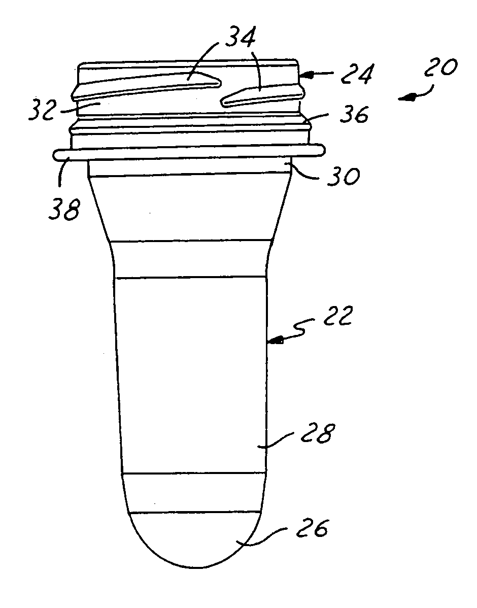
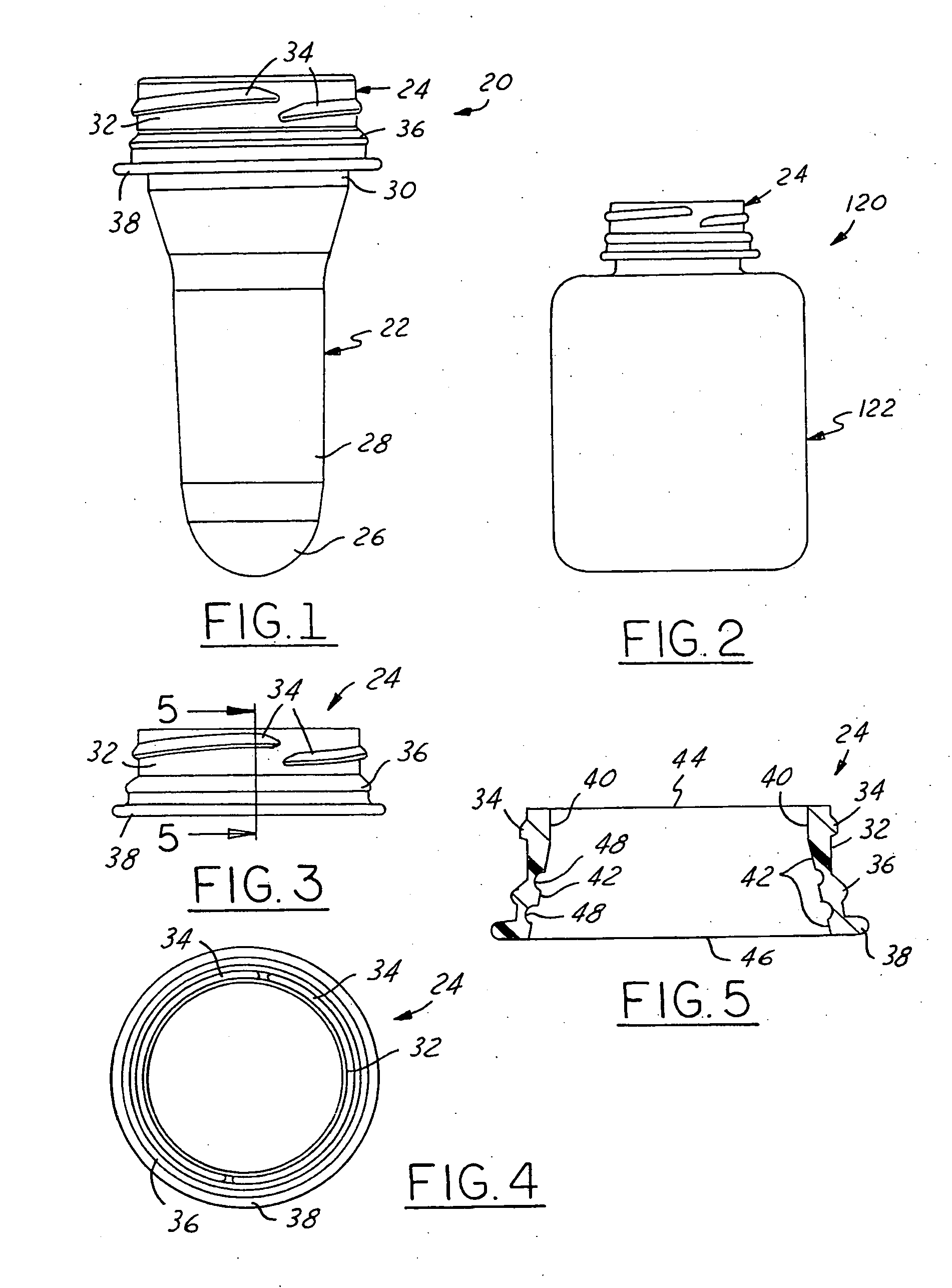
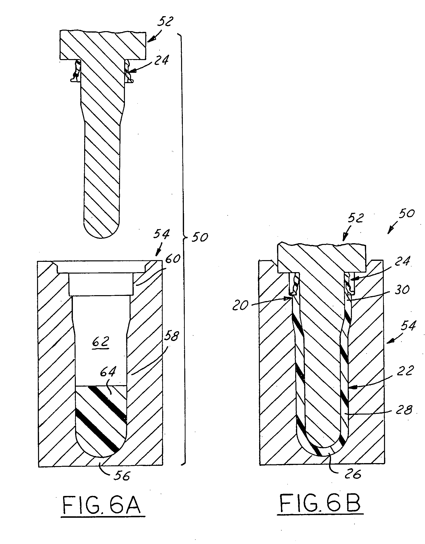
[0017]FIG. 1 illustrates a preform assembly 20 in accordance with one presently preferred embodiment of the invention as comprising a preform 22 and a separate finish ring 24 secured thereover. The preform 22 may be injection molded, but is preferably produced by compression molding as will be discussed in greater detail below. The preform 22 is composed of any suitable plastic material such as monolayer polyethylene terephthalate (PET) or the like, or multilayer PET or the like in which matrix layers of PET, for example, alternated with one or more layers of a barrier resin material such as ethylene vinyl alcohol (EVOH), nylon or the like. The finish ring 24 is injection or compression molded or the like, and is composed of any desired material such as PET, post consumer resin (PCR), process regrind (REG), polypropylene (PP), polyethylene (PE), polyethylene napthalate (PEN), or the like. Preferably, however, the finish ring 24 is composed of a material different than that of the pr...


PUM

PropertyMeasurementUnit
Diameteraaaaaaaaaa

Abstract

A method of making a preform assembly including providing a finish ring of plastic construction, placing the finish ring onto a core pin, introducing a preform polymer into a mold cavity that includes the core pin, and compression molding the preform polymer to the finish ring. A resulting preform assembly, and container assembly blow-molded from the preform assembly, are also disclosed.

Description

[0001] The present invention is directed to preform assemblies for blow molding plastic container assemblies, to plastic container assemblies blow molded from such preform assemblies, and to methods of making such preform assemblies and container assemblies. BACKGROUND AND SUMMARY OF THE INVENTION [0002] In the manufacture of plastic containers, it is conventional to injection mold or compression mold a container preform having a body and a neck finish with one or more external threads or other closure attachment means. The preform neck finish typically is molded to its final geometry, while the body of the preform subsequently is blow molded to the desired geometry of the container body. The preform may be of monolayer construction, or may be of multilayer construction in which one or more intermediate layers in the preform body may or may not extend into the neck finish of the preform. U.S. Pat. Nos. 4,609,516, 4,710,118 and 4,954,376 illustrate injection molding of multilayer con...

Claims


Application Information

Patent Timeline
IPC IPC(8): B29C43/18B29C49/00B65D1/02
CPCB29B11/08Y10T428/1397B29B11/14B29B2911/1402B29B2911/14026B29B2911/14033B29B2911/1404B29B2911/14053B29B2911/1406B29B2911/14066B29B2911/1408B29B2911/14093B29B2911/14113B29B2911/1412B29B2911/14126B29B2911/14146B29B2911/14153B29B2911/14226B29B2911/14233B29B2911/14326B29B2911/14333B29B2911/1444B29B2911/14466B29B2911/1458B29C43/18B29C49/0073B29K2023/06B29K2023/086B29K2023/12B29K2067/00B29L2001/00B65D1/023B29B11/12B29C2949/3009B29C2949/3016B29C2949/302B29C2949/26B29C2949/24B29C2949/28B29C2949/22B29C2949/3008B29C2949/3012B29C2949/3026B29C2949/303B29C2949/3036B29C2949/3028B29C2949/3038B29C2949/306B29C2949/3062B29C2949/0731B29C2949/0722B29C2949/072B29C2949/0733B29C2949/073B29C2949/0801B29C2949/0777B29C2949/0773B29C49/071B29C2949/0715
Inventor BARKER, KEITH J.KALMOUNI, BASSAM M.LYNCH, BRIAN A.MANI, NIKHILNAHILL, THOMAS E.
Owner GRAHAM PACKAGING PET TECH
Learn More