
Method and apparatus for producing oriented plastic strap

Active Publication Date: 2005-10-06
SIGNODE IND GRP
View PDF2 Cites 9 Cited by
  • Summary
  • Abstract
  • Description
  • Claims
  • Application Information

AI Technical Summary

Benefits of technology

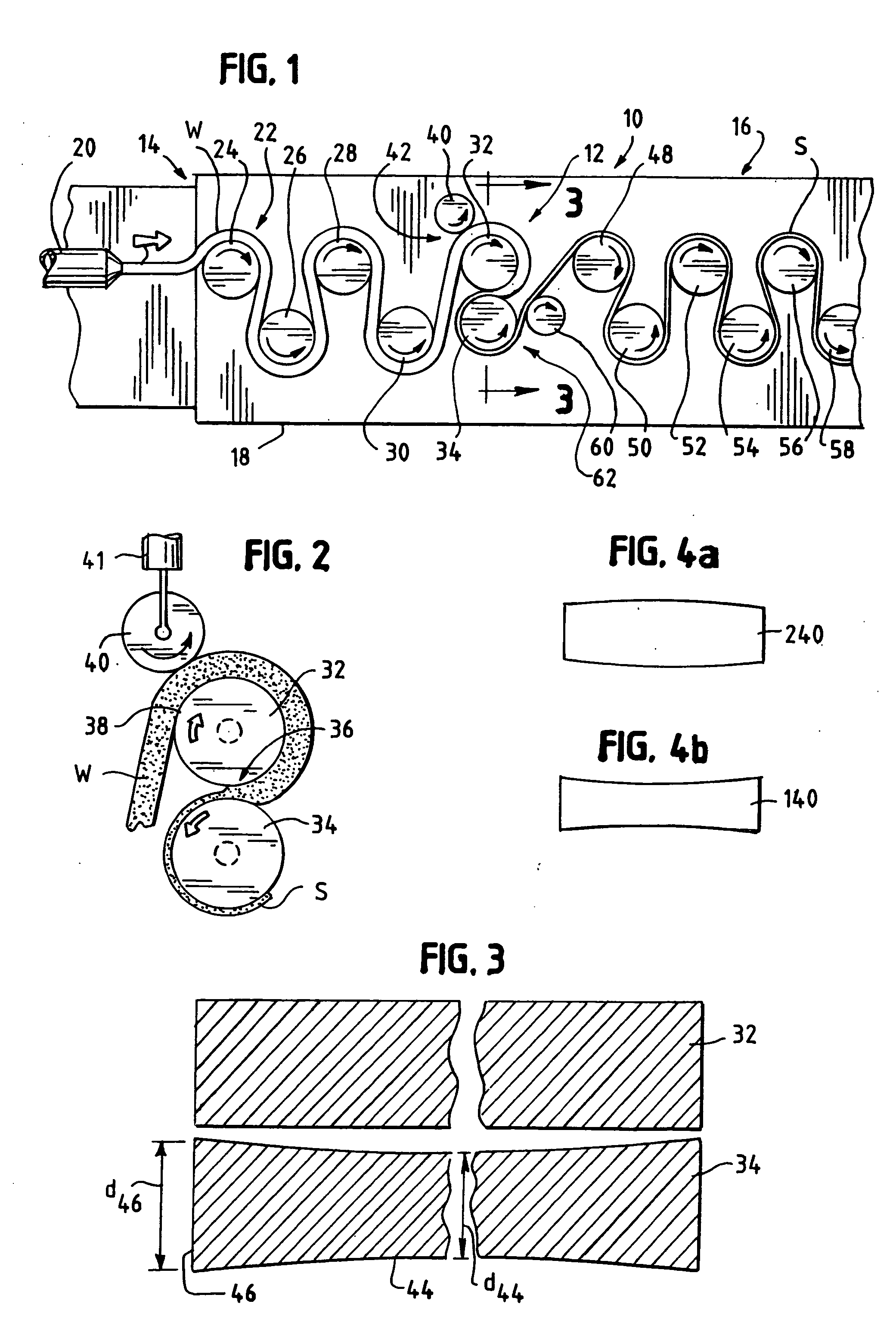
[0012] The pinch roller can be formed having a convex surface to facilitate reducing the entrainment of air in the center of the sheet-strap. Alternately, the pinch roller can be formed having a concave surface to facilitate reforming the edges of the sheet-strap.
[0013] The deaerating nip formed by the pinch roller and the first work roller serves to flatten surface irregularities to prevent air from being entrained between the sheet and the work rollers. This has the effect of reducing thermal and heat transfer inconsistencies between the rollers and the sheet.
[0014] In a preferred method, the pinch roller is rotated at a speed to match the lineal surface velocity of the pinch roller with the lineal surface velocity of the first work roller. To effect preventing air entrainment, the sheet is compressed between the pinch roller and the first work roller. The pressure exerted by the pinch roller on the sheet-strap can be controlled by an air regulator (controlling a pneumatic cylinder), or like means.
[0015] The method can include milling and stretching the sheet between a flat first work roller and a concave-profile second work roller. This configuration “works” the edges of the sheet to a greater extent than the central region of the sheet. In addition, the method can include cooling the sheet immediately as its exits the milling and stretching operation, that is immediately downstream of exiting the second work roller. This prevents over-working or over-stretching the sheet. Cooling can be carried out by contact with a chill roller. An apparatus for carrying out the method is also disclosed.

Problems solved by technology

This resulted in uneven thermal, e.g., heat transfer, properties across the lateral width of the roller / sheet interface.
As a result, the amount of elongation of the sheet-strap (as during the working of the sheet-strap) was not as controlled as desired.

Method used


Image

  • Method and apparatus for producing oriented plastic strap
  • Method and apparatus for producing oriented plastic strap

Examples


Embodiment Construction

[0021] While the present invention is susceptible of embodiment in various forms, there is shown in the figures and will hereinafter be described a presently preferred embodiment with the understanding that the present disclosure is to be considered an exemplification of the invention and is not intended to limit the invention to the specific embodiment illustrated.

[0022] It should be further understood that the title of this section of this specification, namely, “Detailed Description Of The Invention”, relates to a requirement of the United States patent Office, and does not imply, nor should be inferred to limit the subject matter disclosed herein.

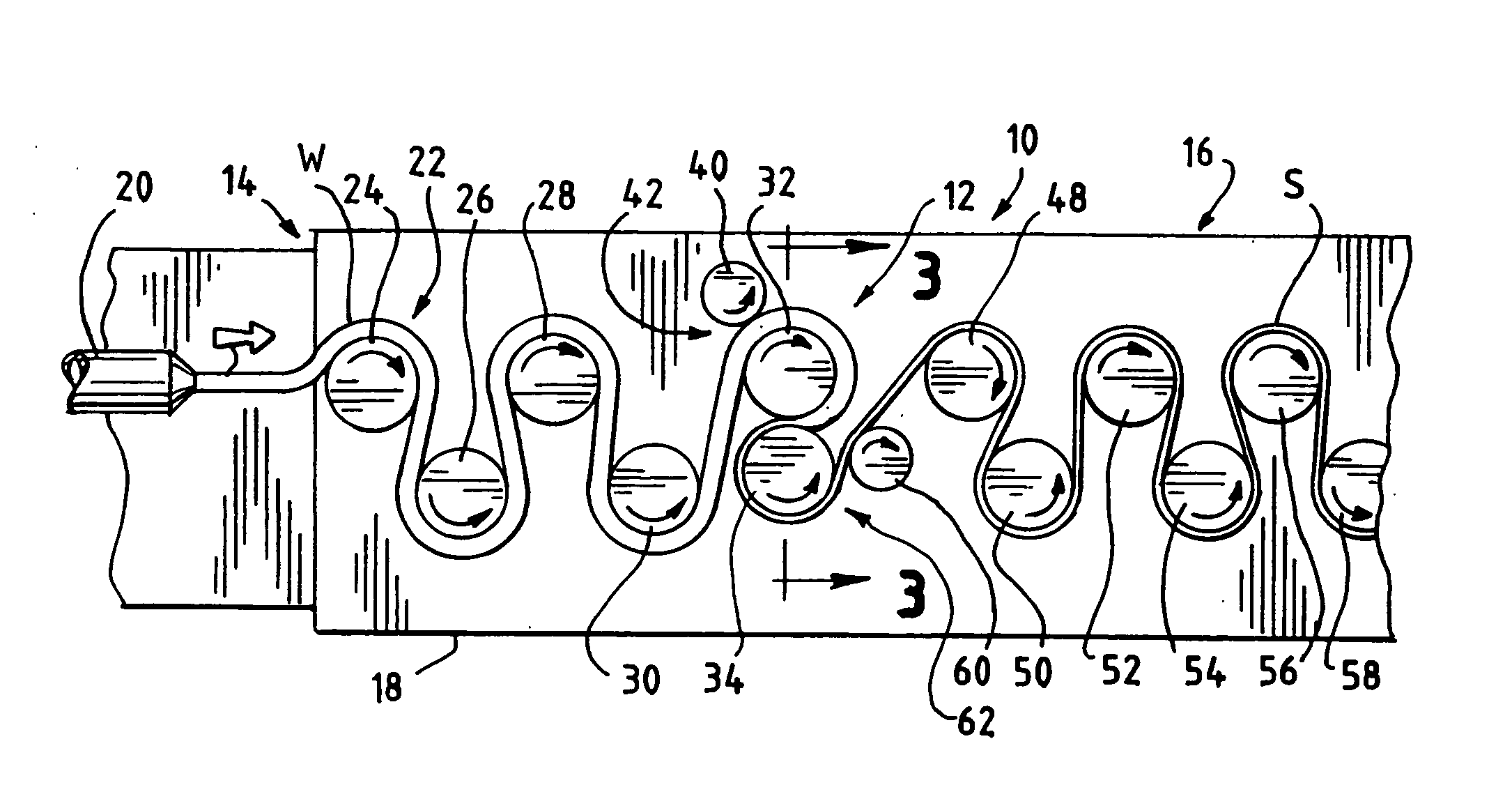
[0023] Illustrated schematically in FIG. 1, is an apparatus 10 for milling and stretching or elongating a sheet or workpiece W into a thin strap stock material. The general arrangement and operation of such an apparatus 10 and method are described in Van Erden et al., U.S. Pat. No. 5,387,388, which is commonly assigned with the presen...


PUM

PropertyMeasurementUnit
Thicknessaaaaaaaaaa
Pressureaaaaaaaaaa
Diameteraaaaaaaaaa

Abstract

A method of producing a plastic sheet-strap includes the steps of providing first and second work rollers such that the work rollers rotate in opposite directions and at different lineal surface velocities. The work rollers are spaced apart with respect to each other so as to define a work roller nip therebetween. A pinch roller is provided that is operably associated with the first work roller. The pinch roller and the first roller defining a deaerating nip therebetween. A solid sheet of material having a thickness is fed into the deaerating nip. The material is pinched against the first work roller and moves with rotation of the first work roller to the work roller nip between the first and second work rollers. The material is simultaneously milled and stretched substantially at the nip during a single pass of the solid sheet material through the nip as the rollers rotate in opposite directions and at different lineal surface velocities to form a milled and stretched oriented sheet. The second roller has a concave profile to work the edges of the sheet more than a central region of the sheet. A chill roller is disposed downstream of the second work roller to cool the milled and stretched oriented sheet.

Description

BACKGROUND OF THE INVENTION [0001] The present invention is directed to a method and apparatus for producing oriented plastic strap. More particularly, the present invention is directed to a method and apparatus for milling and stretching a plastic sheet into strap stock material having a predetermined and consistent desired thickness. [0002] Plastic strap is often used to package items in a bundle, on a pallet or in a crate for shipping, storage and merchandising. The strap is applied in a tensioned loop by an automatic or manually operated strapping machine. In a typical manufacturing process, a cast sheet of thermoplastic material, for example, polypropylene, is first reduced in size by rolling it through a pair of closely spaced milling rollers or cylinders that rotate in opposite directions. After the thickness of the sheet is reduced, the sheet is drawn and stretched out of the milling rollers by a series of orienting rollers or a bridle assembly to its final desired size. [00...

Claims


Application Information

Patent Timeline
IPC IPC(8): B29C43/24B29C53/16B29C55/06B29C55/18B29D7/00
CPCB29C55/18B29C55/06
Inventor VAN ERDEN, DONALD L.KNIOLA, JAMES M.RINEHART, KENNETH C.WEBER, OTTO G.
Owner SIGNODE IND GRP
Learn More