Rotor for dynamo-electric machine

Inactive Publication Date: 2005-10-06
MITSUBISHI ELECTRIC CORP
View PDF8 Cites 30 Cited by
  • Summary
  • Abstract
  • Description
  • Claims
  • Application Information

AI Technical Summary

Benefits of technology

[0005] The present invention provides a rotor for a rotary electric machine having a coil field having a uniform outside diameter that is less likely to collapse by constructing the coil field by winding a coil wire into multiple layers on a bobbin so as to make the numbe

Problems solved by technology

However, in conventional methods for manufacturing rotor coils, no consideration has been given to relationships between axial dimensions of the drum portion 1a and a diameter of the wire material 4, positional relationships between the wire material 4 in radially-adjacent layers, etc.
As a result, one disadvantage has been that the wire material 4 positioned at the outermost circumference of the coil field where

Method used


Image

  • Rotor for dynamo-electric machine
  • Rotor for dynamo-electric machine
  • Rotor for dynamo-electric machine

Examples


Example

Embodiment 1

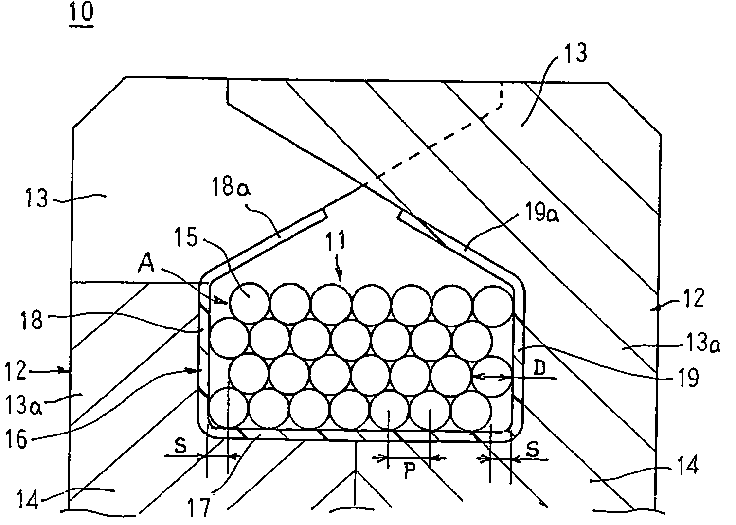
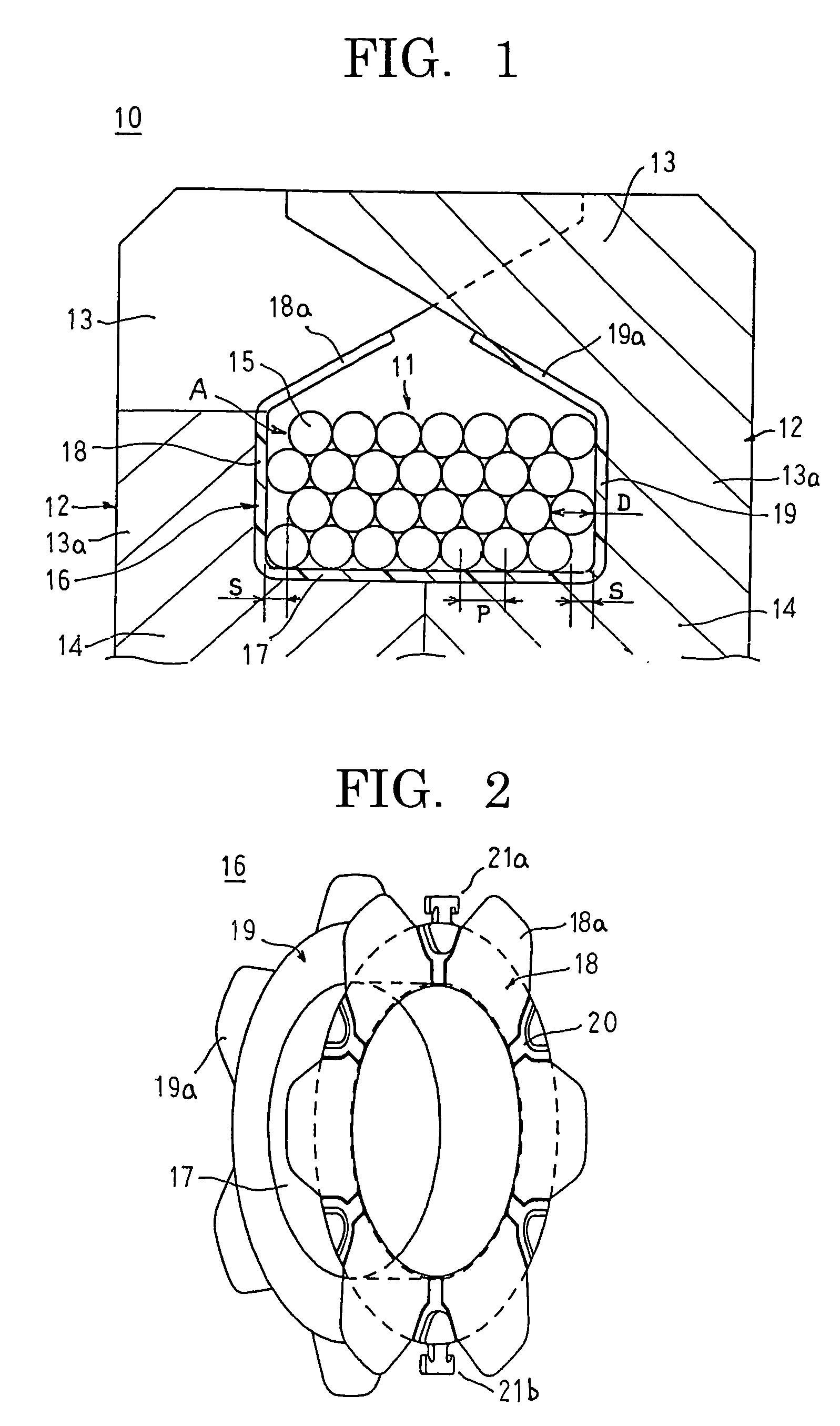
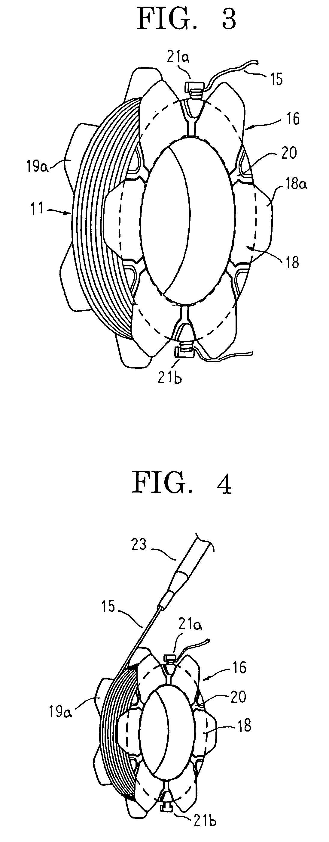
[0026]FIG. 1 is a cross section showing part of a rotor for a rotary electric machine according to Embodiment 1 of the present invention, FIG. 2 is a perspective showing a bobbin used in the rotor for the rotary electric machine according to Embodiment 1 of the present invention, FIG. 3 is a perspective showing a rotor coil installed on the bobbin in the rotor for the rotary electric machine according to Embodiment 1 of the present invention, FIG. 4 is a perspective explaining a method for installing the rotor coil in the rotor for the rotary electric machine according to Embodiment 1 of the present invention, and FIGS. 5 to 7 are process diagrams explaining the method for installing the rotor coil in the rotor for the rotary electric machine according to Embodiment 1 of the present invention. FIGS. 8 to 10 are cross sections showing the rotor coil installed in the rotor for the rotary electric machine according to Embodiment 1 of the present invention, FIG. 8 showing a...

Example

Embodiment 2

[0046]FIG. 11 is a cross section showing a rotor coil installed in a rotor for a rotary electric machine according to Embodiment 2 of the present invention. Moreover, FIG. 11 is a longitudinal section passing through a crossover point C arising when a coil wire 15 is wound into a fourth layer.

[0047] In Embodiment 2, a coil field A of a rotor coil 11, as shown in FIG. 11, is constructed such that a coil wire 15 is installed on a drum portion 17 of a bobbin 16 in four layers of seven columns, and crossover points C do not overlap in a radial direction.

[0048] In odd numbered layers of the coil field A, the coil wire 15 is wound such that a first turn is wound in contact with the inner peripheral wall surface of the first flange portion 18, then a total of seven turns are made at an array pitch P (=D) so as to contact each other, and there is a gap S (=D / 2) between the seventh turn of the coil wire 15 and the inner peripheral wall surface of the second flange portion 19. ...

Example

Embodiment 3

[0053]FIG. 12 is a plan showing part of a bobbin in a rotary electric machine according to Embodiment 3 of the present invention, and FIG. 13 is a cross section explaining an installed state of a rotor coil in the rotary electric machine according to Embodiment 3 of the present invention.

[0054] In Embodiment 3, as shown in FIG. 12, ridge portions 25a making approximately one turn around a drum portion 17A of a bobbin 16A are disposed at an array pitch of (D+G) in an axial direction on an outer circumferential wall surface of the drum portion 17A. Thus, six guiding grooves 25 partitioned by the ridge portions 15a for guiding coil wire are disposed side by side in an axial direction at an array pitch of (D+G) on the drum portion 17A. An internal shape of each of the guiding grooves 25 is formed so as to be equivalent to an external shape of the coil wire 15. Each of the ridge portions 25a is purposely not formed over a predetermined circumferential range of the drum port...


PUM


Abstract

The present invention provides a rotor for a rotary electric machine that suppresses the occurrence of winding disturbances in the process of winding a coil wire and has a coil field having a uniform outside diameter that is less likely to collapse. A coil field of a rotor coil is constructed by winding a coil wire having a circular cross section onto an outer circumference of a drum portion of a bobbin in multiple layers so as to make columns in each of the layers equal in number in an axial direction. Odd numbered layers of the coil field are constructed such that the coil wire is wound for approximately one turn around the drum portion in contact with an inner peripheral wall surface of a first flange portion of the bobbin, then wound into a plurality of columns in an axial direction such that the columns of the coil wire contact each other, and the coil wire in a final column forms a gap S relative to an inner peripheral wall surface of a second flange portion of the bobbin, and even numbered layers of the coil field are constructed such that the coil wire is wound for approximately one turn around the drum portion in contact with an inner peripheral wall surface of the second flange portion, then wound into a plurality of columns in an axial direction such that the columns of the coil wire contact each other, and the coil wire in a final column forms a gap S relative to an inner peripheral wall surface of the first flange portion. The gap S satisfies an expression D/4≦S≦D/2 relative to a diameter D of the coil wire. Thus, because the occurrence of winding disturbances in the process of winding the coil wire is suppressed, the coil wire can be wound into an aligned state, enabling a coil field that is less likely to collapse to be achieved, and the outside diameter of the coil field is made uniform, also preventing damage to an electrically-insulating coating resulting from contact with claw-shaped magnetic poles.

Description

TECHNICAL FIELD [0001] The present invention relates to a rotor for a rotary electric machine mounted to an automotive vehicle such as a passenger car, a truck, an electric train, etc., and particularly to a winding construction of a rotor coil wound onto a drum portion of a bobbin. BACKGROUND ART [0002]FIG. 17 is a front elevation explaining a conventional method for manufacturing a rotor coil of a rotary electric machine such as that described in Japanese Patent Laid-Open No. HEI 6-181139 (Gazette), for example. [0003] In this conventional method for manufacturing a rotor coil, as shown in FIG. 17, a bobbin 1 in which a pair of flanges 1b are formed at two ends of a drum portion 1a is mounted to a spindle 2 and rotated as indicated by the arrow. Then, a wire material 4 is paid out through a nozzle 3 and wound onto the drum portion 1a of the rotating bobbin 1. Here, the rotor coil is obtained by reciprocating the nozzle 3 in the direction of the arrows such that the wire material 4...

Claims


Application Information

Patent Timeline
IPC IPC(8): H01F41/06H02K3/12H02K3/18H02K3/52H02K15/095
CPCH01F41/0633H01F41/0687H02K15/095H02K3/528H02K3/18H01F41/082H01F41/098H02K3/12H02K3/04
Inventor NAKANISHI, TOSHIOONO, MASASHITAKIZAWA, TAKUSHIOOHASHI, ATSUSHITANAKA, KATSUNORI
Owner MITSUBISHI ELECTRIC CORP
Why Eureka
Try Eureka