Combined sensor and bearing assembly and method of magnetizing element of rotation sensor

a technology of rotating sensor and bearing, which is applied in the direction of instruments, mechanical devices, devices using electric/magnetic means, etc., can solve the problems of difficult positioning of signal processing circuit adjacent to the rotation sensor unit, lack of stability of magnetic field used therein, and difficulty, so as to achieve advantageously increase the magnetic intensity

Active Publication Date: 2005-10-06
NTN CORP
View PDF2 Cites 14 Cited by
  • Summary
  • Abstract
  • Description
  • Claims
  • Application Information

AI Technical Summary

Benefits of technology

[0008] In view of the foregoing, a primary object of the present invention is to provide an improved combined sensor and bearing assembly effective to accomplish a precise detection of the absolute position of the angle of rotation within a limited range of angle and capable of being assembled compact in size.
[0009] Another important object of the present invention is to provide a method of magnetizing a to-be-detected member of a rotation sensor unit, which is effective to precisely magnetize the to-be-detected member of the rotation sensor unit.

Problems solved by technology

Positioning of the signal processing circuit adjacent the rotation sensor unit is difficult to achieve because of a limited space available and an additional problem is involved in designing in a compact size the machine in which the combined sensor and bearing assembly is incorporated.
Although magnetization with an air-core coil is well known in the art, the magnetic field used therein lacks stability and, therefore, difficulty has been encountered with to magnetize the magnet to represent a magnetic intensity distribution resembling the sinusoidal waveform.
Also, what is disclosed in the third mentioned patent publication is a mere magnetic angle detecting device and no rolling bearing assembly for rotatably supporting a shaft member is employed therein and, accordingly, there is a high risk that the precision may lower as a result of a mechanical frictional wear occurring in an insertion hole or the like for the passage of a shaft member of a housing therethrough even though the sensor unit is designed to be of a non-contact type.

Method used


Image

  • Combined sensor and bearing assembly and method of magnetizing element of rotation sensor
  • Combined sensor and bearing assembly and method of magnetizing element of rotation sensor
  • Combined sensor and bearing assembly and method of magnetizing element of rotation sensor

Examples


Embodiment Construction

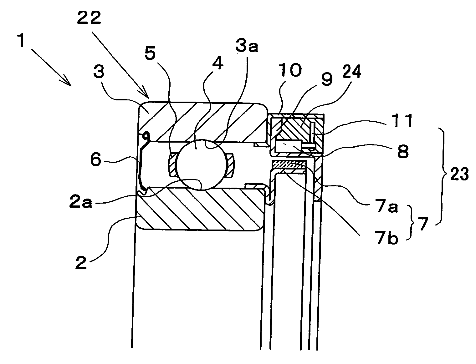
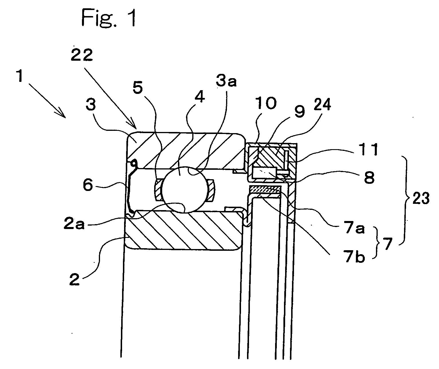
[0043] A combined sensor and bearing assembly according to a first preferred embodiment of the present invention will now be described with particular reference to FIGS. 1 to 6. The combined sensor and bearing assembly identified by 1 includes a rolling bearing unit 22 and a rotation sensor unit 23 integrated into the rolling bearing unit 22. The rolling bearing unit 22 includes a rotatable raceway member 2 having at least one inner raceway 2a defined in an outer peripheral surface thereof, a non-rotatable or stationary raceway member 3 having an outer raceway 3a defined in an inner peripheral surface thereof and positioned around the rotatable raceway member 2 with an annular bearing space defined between it and the rotatable raceway member 2, and a circular row of rolling elements 4 rollingly accommodated within the annular bearing space and received in part within the inner raceway 2a and in part within the outer raceway 3a.

[0044] The rotation sensor unit 23 is disposed at one o...


PUM


Abstract

A combined sensor and bearing assembly (1) of the present invention includes a rolling bearing unit (22) and a rotation sensor unit (23). The rolling bearing unit (22) includes a rotatable raceway member (2), a stationary raceway member (3) mounted around the rotatable raceway member (2) with an annular bearing space defined between it and the rotatable raceway member (2), and a circular row of rolling elements (4). The combined sensor and bearing assembly (1) also includes a to-be-detected member (7) including a magnet secured to the rotatable raceway member (2), and a magnetic detector (8) including a magnetic sensor of an analog output type disposed in face-to-face relation with the to-be-detected member (7). Only a range in which a magnetic characteristic of the to-be-detected member (7) relative to the magnetic detector (8) exhibits linearity is used for detection of rotation angle of the rotatable raceway member (2).

Description

BACKGROUND OF THE INVENTION [0001] (Field of the Invention) [0002] The present invention relates to a combined sensor and bearing assembly installed in any of various machines and equipments for detecting the rotation of a rotating mechanism within, for example, a limited range of angle, and a method of magnetizing a rotation sensor unit employed in the combined sensor and bearing assembly. [0003] (Description of the Prior Art) [0004] The rotation sensor unit used in the combined sensor and bearing assembly has been well known in the art from, for example, the Japanese Laid-open Patent Publications No. 2004-004028 and No. 2004-20548, in which along with the rotation of a rotatable race two, 90° phase offset sinusoidal outputs are obtained in the form of a sine wave signal and a cosine wave signal so that the tangent value can be obtained from those signals to detect the absolute position of rotation angle of the rotatable race. [0005] Also, irrespective of the bearing, an independen...

Claims


Application Information

Patent Timeline
Patent Type & Authority Applications(United States)
IPC IPC(8): G01D5/245F16C19/52F16C33/58F16C41/00G01P3/44G01P3/487
CPCG01D5/2451G01P3/443F16C19/06F16C41/007G01P3/487
Inventor KOIKE, TAKASHIISHIKAWA, TOMOMIISOBE, HIROSHI
Owner NTN CORP
Why Eureka
Try Eureka