Method and apparatus for processing three-dimensional images

a three-dimensional image and processing method technology, applied in the field of stereo image processing technology, can solve the problems of falling behind in the expansion of the possibilities of expression itself, and particular technology is not intended to realize a high speed for the whole of the 3d display processing, and achieve the effect of high-speed processing

Inactive Publication Date: 2005-10-06
SANYO ELECTRIC CO LTD
View PDF24 Cites 91 Cited by
  • Summary
  • Abstract
  • Description
  • Claims
  • Application Information

AI Technical Summary

Benefits of technology

[0016] The depth value acquiring unit may acquire the range of calculation region in the depth direction at a resolution lower than that of the viewpoint images. The depth value acquiring unit may acquire the range of calculation region in the depth direction, by using an object which corresponds to the object to be displayed three-dimensionally and which has a small amount of data. According to this mode of carrying out the present invention, a processing amount required for acquiring the range of calculation region in the depth direction is reduced, so that a high speed processing as a whole can be realized.

Problems solved by technology

In recent years, inadequacy of network infrastructure has often been an issue, but in this time of transition toward broadband age, it is rather the inadequacy in the kind and number of contents utilizing broadband that is drawing more of our attention.
In contrast, technical attempts at expanding the possibilities of expression itself seem to be falling behind.
This particular technology, however, is not intended to realize a high speed for the 3D display processing as a whole.

Method used


Image

  • Method and apparatus for processing three-dimensional images
  • Method and apparatus for processing three-dimensional images
  • Method and apparatus for processing three-dimensional images

Examples


first embodiment

[0059] A first embodiment of the present invention will be outlined below. According to the first embodiment, a viewpoint, such as a camera, is disposed temporarily in an object space. The range of calculation area in the depth direction for an object to be displayed three-dimensionally can be obtained by the camera thus placed temporarily (hereinafter referred to simply as “temporary camera”). In obtaining this range of calculation area in the depth direction, an apparatus according to the first embodiment uses a known algorithm of hidden surface removal which is called the z-buffer method. The z-buffer method is a technique such that when the z-values of an object are to be stored for each pixel, the z-value already stored is overwritten by any z-value closer to the viewpoint on the Z axis. The range of calculation area in the depth direction is specified by obtaining the maximum z-value and the minimum z-value among the z-values thus stored for each pixel (hereinafter referred to...

second embodiment

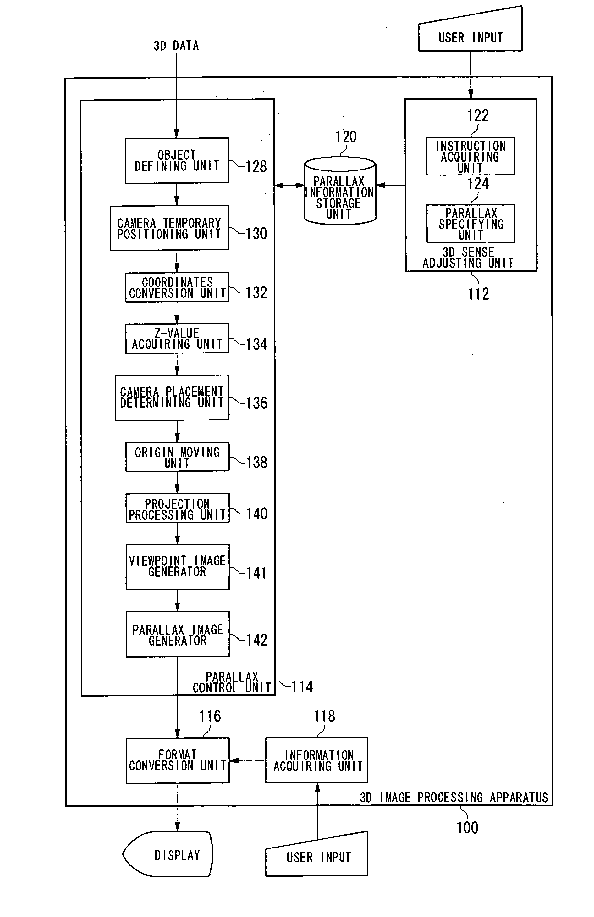
[0096] A second embodiment of the present invention will now be outlined hereinbelow. In the first embodiment, z-values are acquired by placing a temporary camera in an object space temporarily, but, according to the second embodiment, z-values acquired by real cameras are used. FIG. 19 illustrates a structure of a three-dimensional image processing apparatus 100 according to the second embodiment. Hereinbelow, the same reference numbers are used to indicate the same features and components as in the first embodiment, and the explanation thereof is omitted as appropriate. The three-dimensional image processing apparatus 100 according to the second embodiment includes components not found in the three-dimensional image processing apparatus 100 according to the first embodiment as shown in FIG. 4, namely, a z-value readout unit 144, a z-value write unit 146 and a z-value storage unit 150. The z-value storage unit 150 stores z-values acquired by a z-value acquiring unit 134. The z-valu...

third embodiment

[0102] A third embodiment of the present invention will now be outlined hereinbelow. The second embodiment proves particularly effective for static objects. However, there may be cases where an object suddenly enters the field of view of a camera of this system or this three-dimensional image processing apparatus detects a scene change. In such a case, there occurs an abrupt change in the range of calculation region, so that it may be inappropriate to use the z-values acquired for the preceding frame as the z-values of the current frame. Then the three-dimensional image processing apparatus according to the third embodiment copes with such a situation by applying camera parameters, which generate parallax images with weaker parallax than that of the parallax images generated for the preceding frame, to the real cameras, instead of setting the camera parameters using the z-values for the preceding frame.

[0103]FIG. 21 illustrates a structure of a three-dimensional image processing ap...


PUM


Abstract

A camera placement determining unit determines a position at which a real, camera is placed in an object space, based on a z-value acquired in a frame immediately preceding a current frame and a user's appropriate parallax. After a projection processing, a parallax image generator generates parallax images based on viewpoint images. The z-value is acquired, in the immediately preceding frame, by at least one real camera positioned by the camera placement determining unit. Using this z-value in the current frame, the high-speed processing of three-dimensional images as a whole can be achieved.

Description

BACKGROUND OF THE INVENTION [0001] 1. Field of the Invention [0002] The present invention relates to a stereo image processing technology, and it particularly relates to method and apparatus for producing stereo images based on parallax images. [0003] 2. Description of the Related Art [0004] In recent years, inadequacy of network infrastructure has often been an issue, but in this time of transition toward broadband age, it is rather the inadequacy in the kind and number of contents utilizing broadband that is drawing more of our attention. Images have always been the most important means of expression, but most of the attempts so far have been at improving the quality of display or data compression ratio. In contrast, technical attempts at expanding the possibilities of expression itself seem to be falling behind. [0005] Under such circumstances, three-dimensional image display (hereinafter referred to simply as “3D display” also) has been studied in various manners and has found p...

Claims


Application Information

Patent Timeline
Patent Type & Authority Applications(United States)
IPC IPC(8): G06F15/80G06T19/00H04N13/128
CPCH04N13/0003H04N13/0018H04N13/0289H04N13/0029H04N13/0275H04N13/0022H04N13/289H04N13/275H04N13/122H04N13/10H04N13/128H04N13/139
Inventor MASHITANI, KENHAMAGISHI, GORO
Owner SANYO ELECTRIC CO LTD
Why Eureka
Try Eureka