Driving control apparatus and method, and exposure apparatus
- Summary
- Abstract
- Description
- Claims
- Application Information
AI Technical Summary
Benefits of technology
Problems solved by technology
Method used
Image
Examples
first embodiment
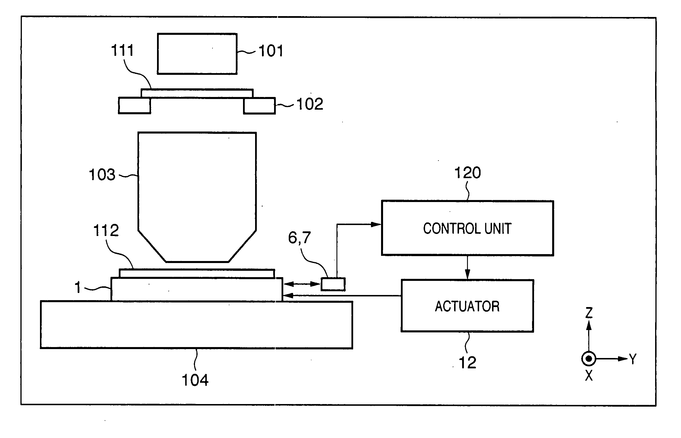
[0025]FIG. 11 is a schematic view showing the schematic arrangement of an exposure apparatus according to the first embodiment. In FIG. 11, a reticle 111 held on a reticle stage 102 is irradiated with exposure light emitted by an illumination unit 101. Exposure light having passed through the reticle 111 enters a projection optical system 103. The projection optical system 103 reduces at a predetermined magnification a pattern image formed by exposure light having passed through the reticle 111, and the reduced pattern image is projected onto a wafer 112 held by a wafer stage 1. The wafer stage 1 two-dimensionally moves on a surface plate 104.
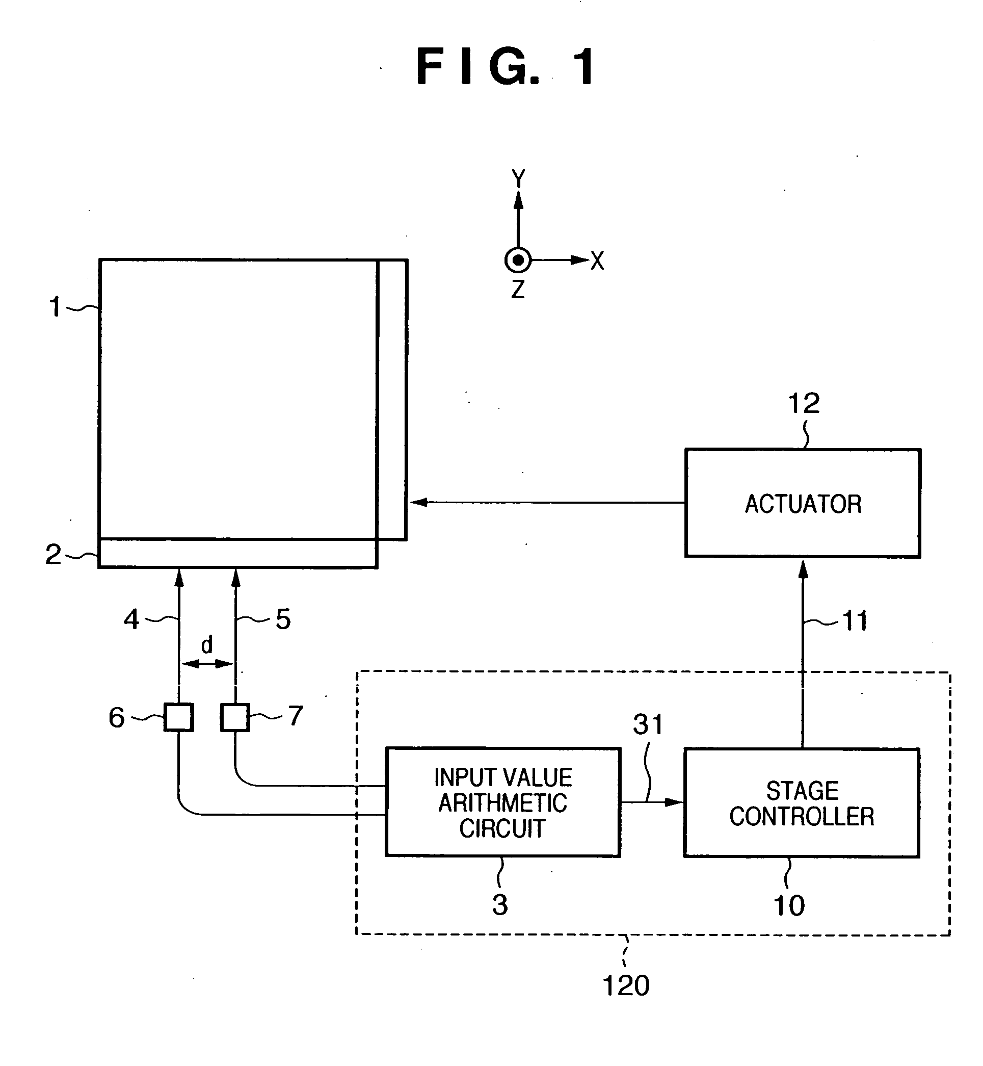
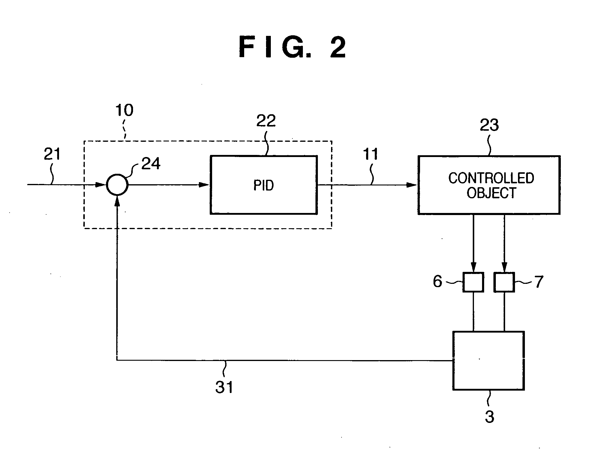
[0026] The position of the wafer stage 1 is measured by laser interferometers 6 and 7 and the like, and measurement values are input to a control unit 120. The control unit 120 outputs a drive signal to an actuator 12 so as to drive the stage to a target position on the basis of the input measurement values. The actuator 12 controls to drive t...
second embodiment
[0040] The average value of measurement values from an interferometer is calculated in the first embodiment, but the average value of rotation amounts may be calculated.
[0041]FIG. 7 is a block diagram showing the arrangement of an input value arithmetic circuit 3 according to the second embodiment. The measurement values of interferometers 7 and 6 are input to a subtractor 92. The subtractor 92 calculates the difference between the input measurement values, and outputs the difference value. Similar to the first embodiment, a plurality of measurement values are acquired by the interferometers 6 and 7 during one control cycle (during the measurement timing of each control cycle), and a plurality of difference values are output from the subtractor 92. An average value calculator 83 averages these difference values, and inputs the average value to a rotation amount arithmetic unit 93. The rotation amount arithmetic unit 93 converts the input difference value into a rotation amount 31 b...
third embodiment
[0045] The rotation amount calculated in the first and second embodiments may be given an arbitrary offset. FIG. 9 shows this state. The offset is used to correct the rotation amount when the rotation amount has a predetermined offset from a true value upon averaging owing to the output characteristic of a sensor.
PUM
 Abstract
Description
Claims
Application Information
 - R&D
- Intellectual Property
- Life Sciences
- Materials
- Tech Scout
- Unparalleled Data Quality
- Higher Quality Content
- 60% Fewer Hallucinations
Browse by: Latest US Patents, China's latest patents, Technical Efficacy Thesaurus, Application Domain, Technology Topic, Popular Technical Reports.
© 2025 PatSnap. All rights reserved.Legal|Privacy policy|Modern Slavery Act Transparency Statement|Sitemap|About US| Contact US: help@patsnap.com


