System and method for the measurement of optical distortions

a technology of optical distortion and measurement method, applied in the direction of optical apparatus testing, instruments, structural/machine measurement, etc., to achieve the effect of improving visual cueing and alignment, improving measurement accuracy and speed of canopy optical deviation data, and accurately reconstructing canopy angular deviations

Inactive Publication Date: 2005-10-06
LOCKHEED MARTIN CORP
View PDF13 Cites 29 Cited by
  • Summary
  • Abstract
  • Description
  • Claims
  • Application Information

AI Technical Summary

Benefits of technology

[0013] The wavefront-error determination provided by the present invention greatly improves the measurement accuracy and speed of canopy optical deviation data. Further, proven wavefront error reconstruction algorithms and associated software can accurately reconstruct canopy angular deviations at any azimuth and elevation for any continuously varying point within the PEV. This enables greatly improved visual cueing and alignment between computer-generated symbology and real world images external to the aircraft that also dynamically accounts for the optical distortions of the aircraft canopy.

Problems solved by technology

When the canopy is in the path of the patterned collimated beams of light, a distorted image results as the aircraft canopy distorts the individual patterned collimated beams of light.
However, a distorted image results when the aircraft canopy is placed in a path of the patterned collimated beams of light and distorts the patterned collimated beam of light.

Method used


Image

  • System and method for the measurement of optical distortions
  • System and method for the measurement of optical distortions
  • System and method for the measurement of optical distortions

Examples


Embodiment Construction

[0029] Preferred embodiments of the present invention are illustrated in the FIGUREs, like numerals being used to refer to like and corresponding parts of the various drawings.

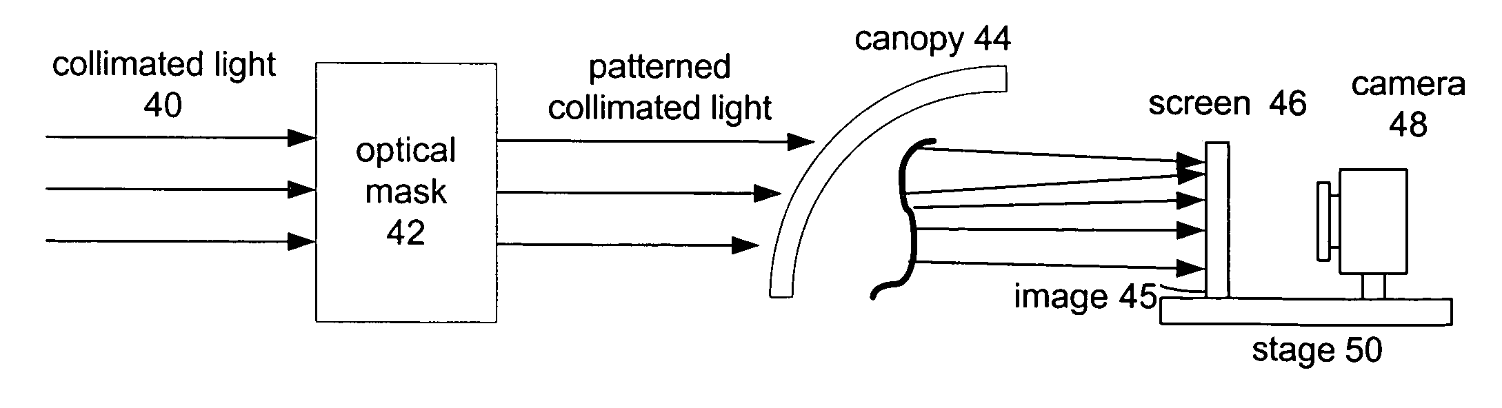
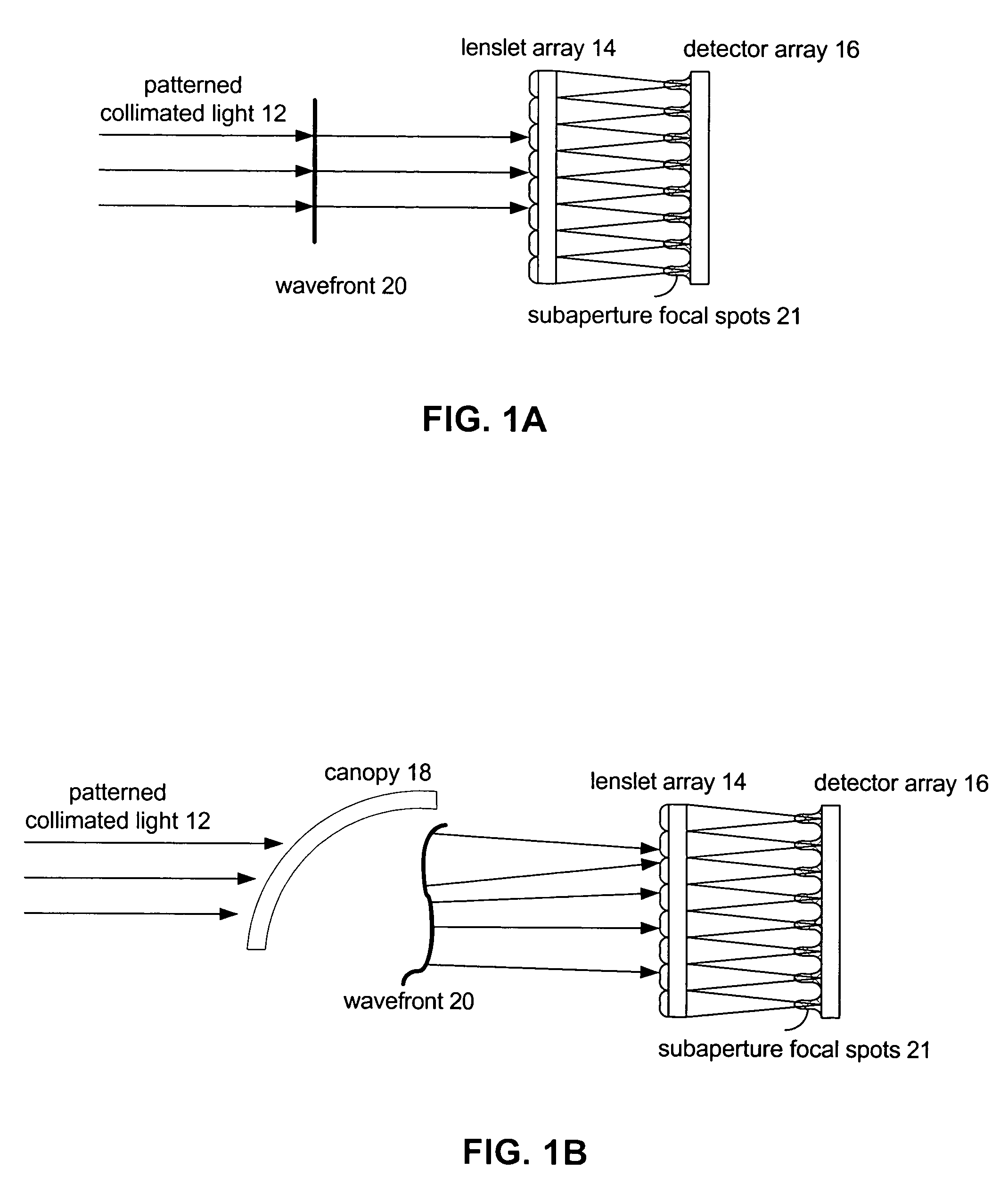
[0030] The present invention provides a means for measuring canopy optical deviations accurately and over a large field of regard (FOR) and large PEV. Additionally, the present invention allows these measurements to be made in a rapid and massively parallel manner when compared to previous methods, as the wavefront errors over the entire PEV are measured and calculated with a single pair of camera images. These improvements in measurement speed and accuracy are coupled with algorithms that dynamically compensate for canopy optical distortion and HMD symbology placement as a function of head position. This results in improved visual cueing and alignment between computer generated symbology and exterior images.

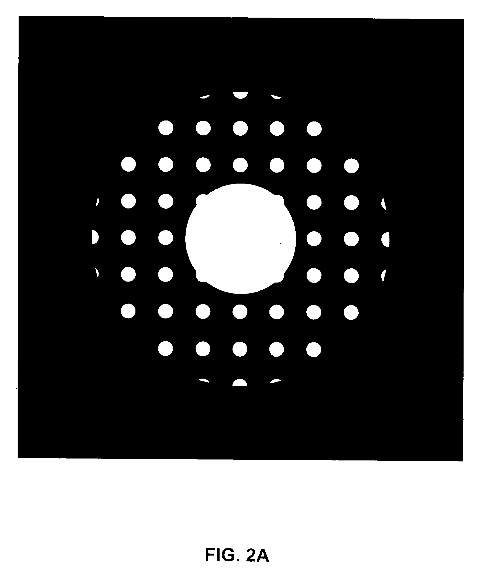
[0031] One embodiment provides a novel concept for canopy characterization and measurement. This conc...


PUM

PropertyMeasurementUnit
frequencyaaaaaaaaaa
optical deviationsaaaaaaaaaa
volumeaaaaaaaaaa

Abstract

An apparatus measures optical deviations caused by an aircraft canopy. In this apparatus, a light source generates a beam of light. A collimator, optically coupled to the light source, then collimates the beam of light. An optical assembly patterns the collimated beam of light into a patterned array of subaperture beams, which is directed onto an imaging screen. The patterned collimated beam of light produces images, which are electronically imaged and recorded to memory. An undistorted image results when the aircraft canopy is not placed in a path of the patterned collimated beam of light. However, a distorted image results when the aircraft canopy is placed in a path of the patterned collimated beam of light and distorts the patterned collimated beam of light. A processing unit compares the distorted image to the undistorted image to determine the optical distortions caused by the aircraft canopy.

Description

TECHNICAL FIELD OF THE INVENTION [0001] The present invention relates generally to the measurement of optical distortions, and more particularly, a system and method to rapidly measure the optical distortions of an aircraft canopy. BACKGROUND OF THE INVENTION [0002] Aircraft canopies protect the pilot from direct exposure to the flight environment while ideally providing the largest possible unobstructed view from the cockpit. In new fighter aircraft, the exterior shapes of the canopy typically include compound curvatures. These compound shapes are imposed by aerodynamic, structural, bird strike safety and electromagnetic signature requirements. In order to satisfy structural and bird strike safety requirements, plastic-based canopies have become quite thick to withstand these stresses. These thick canopies introduce strong refractive optical power and distortion into the view of the outside world. These optical distortions vary with target azimuth, elevation, and the pilot's eye (x...

Claims


Application Information

Patent Timeline
Patent Type & Authority Applications(United States)
IPC IPC(8): G01M11/00G01N21/958
CPCG01M11/00G01N2021/9586G01N21/958
Inventor JONES, MICHAEL I.
Owner LOCKHEED MARTIN CORP
Why Eureka
Try Eureka