Examination apparatus and focusing method of examination apparatus

a technology of examination apparatus and focusing method, which is applied in the direction of mountings, instruments, measurement devices, etc., can solve the problems of specimen bleaching, low fluorescence intensity, and unaccustomed to such operations, and achieve the effect of reducing the fluorescence level of the specimen due to bleaching

Inactive Publication Date: 2005-10-06
OLYMPUS CORP
View PDF3 Cites 27 Cited by
  • Summary
  • Abstract
  • Description
  • Claims
  • Application Information

AI Technical Summary

Benefits of technology

[0012] In light of the problems described above, it is an object of the present invention to provide an examination apparatus and a focusing method for an examination apparatus in which focusing for fluoroscopy can be performed quickly and easily.
[0024] With the present invention, since focusing is performed using reflected light from the surface of the specimen followed by focusing for fluorescence using this focal position as a basis, it is possible to quickly and easily perform fluoroscopy even if the level of fluorescence emitted from the specimen is low, which normally makes focusing difficult.
[0025] Also, with the present invention, since the operations up to focusing for fluorescence can be performed quickly, it is possible to keep any damage to the specimen, such as bleaching, to a minimum, which allows stable and superior fluoroscopy to be realized.

Problems solved by technology

Therefore, this method suffers from the problem that an operator who is unaccustomed to such operations may easily make a mistake.
With such protein-containing specimens, however, the fluorescence intensity is very low.
Therefore, if the focusing in step (a) described above takes too long or if the illumination intensity for quickly carrying out the focusing in step (a) is increased too much, the level of fluorescence from the specimen decreases due to bleaching of the specimen.
This results in a problem in that fluoroscopy cannot be achieved.
In order to more quickly perform detection of the focus position with non-confocal detection, the laser beam intensity can be increased; however, if the laser beam intensity is increased too much, there is a problem in that the fluorescence becomes reduced due to bleaching of the specimen, which makes it difficult to perform fluoroscopy.

Method used


Image

  • Examination apparatus and focusing method of examination apparatus
  • Examination apparatus and focusing method of examination apparatus
  • Examination apparatus and focusing method of examination apparatus

Examples


first embodiment

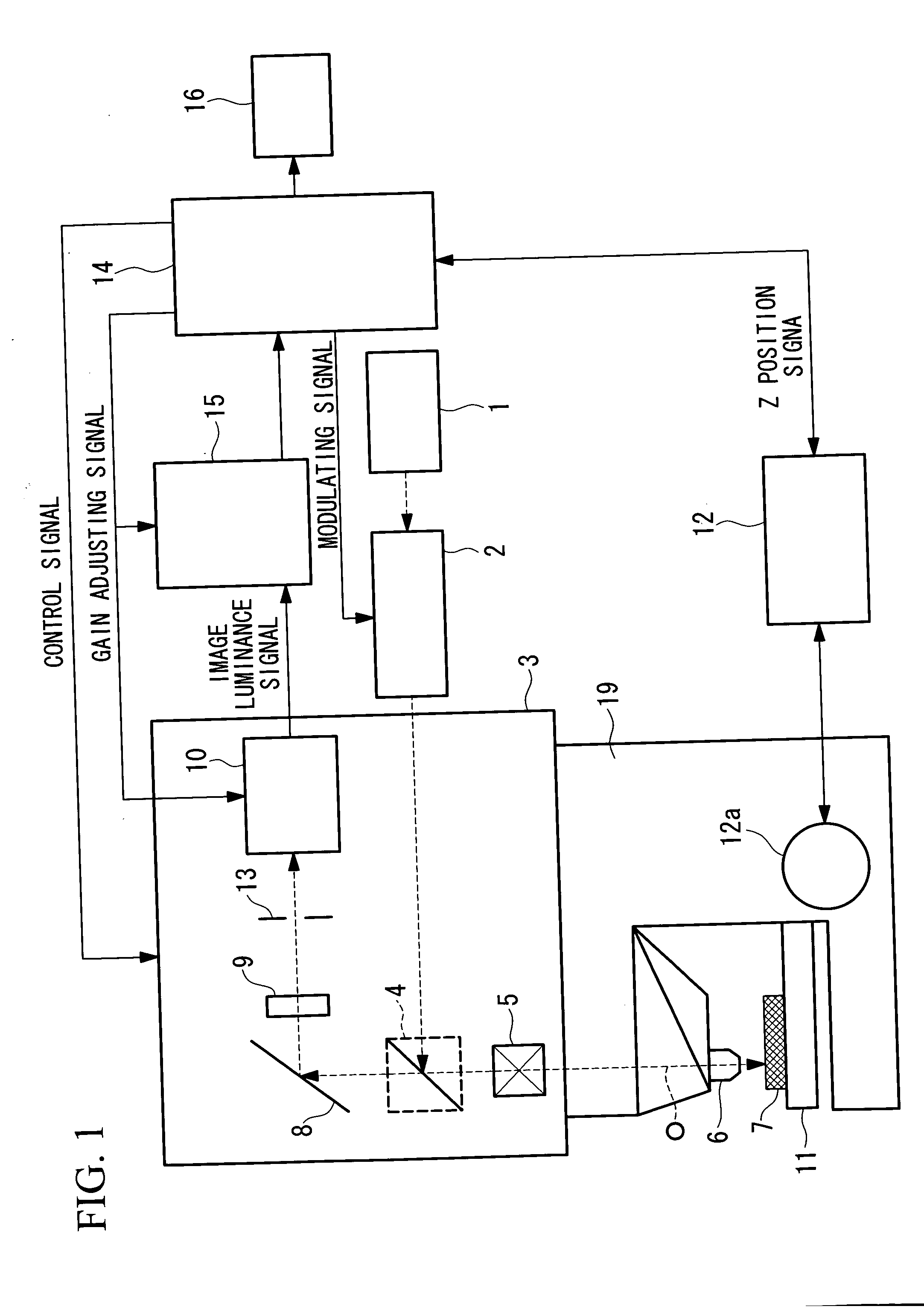
[0040]FIG. 1 schematically shows the configuration of a scanning laser microscope in which a focusing method according to a first embodiment of the present invention is employed.

[0041] In FIG. 1, reference numeral 1 represents a laser light source, and this laser light source 1 generates multispectral laser light.

[0042] A laser modulating unit 2 is disposed in the optical path of the laser light from the laser light source 1. The laser modulating unit 2 is formed, for example, of an AOTF (acousto-optic tunable filter), which can make the laser light from the laser light source 1 monochromatic and can adjust the intensity thereof based on a modulation signal from a system controller 14.

[0043] The laser light emitted from the laser modulating unit 2 is then introduced to an optical unit 3. In the optical unit 3, a cube 4 is disposed in the light path of the laser light emitted from the laser modulating unit 2. The cube 4 is mounted on a turret (not shown) and it can be replaced wit...

second embodiment

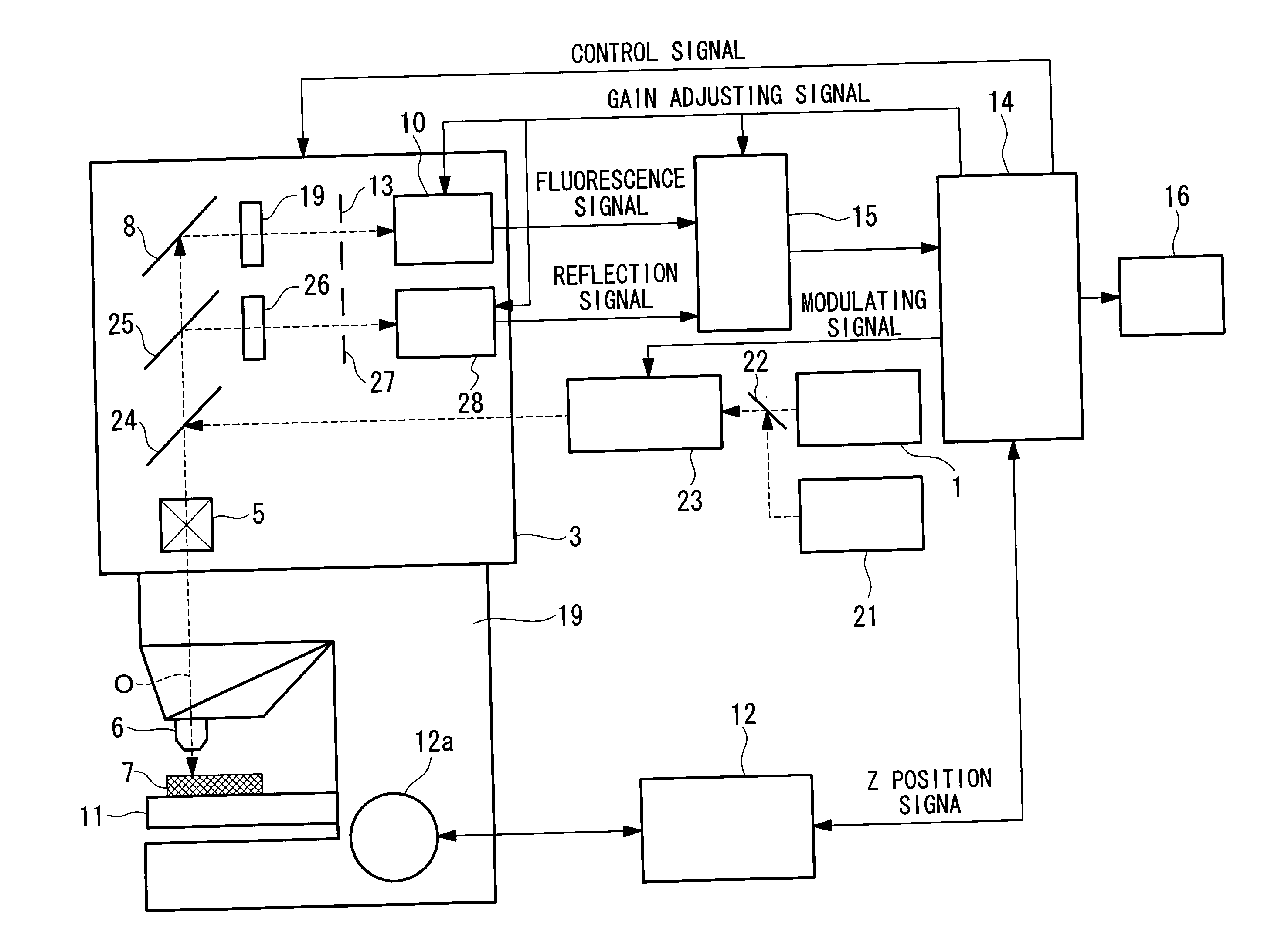
[0068] Next, a second embodiment of the present invention will be described.

[0069]FIG. 4 schematically shows the configuration of a scanning-laser microscope using a focusing method according to the second embodiment of the present invention. The same parts as shown in FIG. 1 are assigned the same reference numerals.

[0070] In this case, a laser light source 21 is provided in addition to the laser light source 1. Also, a half-mirror 22 is disposed in the light path of the laser light from the laser light source 1. Since this half-mirror transmits laser light from the laser light source 1 and reflects laser light from the laser light source 21, the laser beams from the laser light sources 1 and 21 are combined onto the same light path.

[0071] The laser light source 1 is for generating reflected light at the specimen 7. The laser light source 21 is for exciting fluorescence in the specimen 7, and therefore, an optimum light source that matches the excitation wavelength for exciting f...

third embodiment

[0091] Next, a third embodiment of the present invention will be described.

[0092]FIG. 7 schematically shows the configuration of a confocal microscope in which a focusing method according to the third embodiment of the present invention is employed.

[0093] In this case, instead of the laser light source 1, a halogen lamp 31 is provided. The halogen lamp 31 introduces white light into the optical unit 3.

[0094] A cube 32 is disposed in the light path of the white light from the halogen lamp 31. The cube 32 is mounted on a turret (not shown) and can be replaced, either with a motor or manually, with another cube having different characteristics. In this case, a cube having a half-mirror with 20% reflectivity and 80% transmission and cube having a dichroic mirror that reflects light from the halogen lamp 31 and transmits fluorescence from the specimen 7 are used as the cube 32.

[0095] A rotating disk 33 is disposed in the reflection light path of the cube 32. The rotating disk 33 has ...


PUM


Abstract

A focusing method for an examination apparatus that can quickly and easily perform focusing for fluoroscopy is provided. The focusing method, for an examination apparatus that can observe fluorescence emitted from a specimen, includes a first step of irradiating the specimen with light via an objective lens to generate reflected light and fluorescence; a second step of performing focusing with respect to the surface of the specimen using the reflected light from the specimen; and a third step of performing focusing for the fluorescence based on the focal position of the specimen surface in the second step.

Description

BACKGROUND OF THE INVENTION [0001] 1. Field of the Invention [0002] The present invention relates to a focusing method for an examination apparatus, such as a microscope, that can observe fluorescence emitted from a specimen. [0003] 2. Description of Related Art [0004] In the related art, fluorescence microscopes are known examination apparatuses. In fluorescence microscopes, excitation light from a light source is focused onto a specimen by an objective lens, fluorescence emitted from the specimen passes through the objective lens and is focused by an imaging lens, and the fluorescence is transmitted through a prism disposed inside a lens barrel to form an image. [0005] In the fluoroscopy carried out with such a fluorescence microscope, the following steps are performed: (a) first, the specimen is initially focused; (b) next, the illumination intensity of the light source is reduced; (c) at the same time, the sensitivity of a photosensor is increased; and (d) the focal position is ...

Claims


Application Information

Patent Timeline
Patent Type & Authority Applications(United States)
IPC IPC(8): G02B21/00G02B21/06G02B21/24G02B21/36
CPCG02B21/245G02B21/002
Inventor KAWANO, YOSHIHIROISHIBE, ISAOTANIKAWA, YOSHIHISATSUCHIYA, ATSUHIRO
Owner OLYMPUS CORP
Why Eureka
Try Eureka