
Device for driving an endless belt and image forming apparatus using the same

a technology of endless belts and forming apparatuses, applied in the direction of electrographic processes, instruments, gearing, etc., can solve the problems of insufficient accuracy of inability to provide the accurate inability to accurately provide the diameter of the drum, etc., to achieve accurate register of toner images and rotate stably

Inactive Publication Date: 2005-10-06
KOIDE HIROSHI
View PDF7 Cites 9 Cited by
  • Summary
  • Abstract
  • Description
  • Claims
  • Application Information

AI Technical Summary

Benefits of technology

"The present invention provides a device for driving an endless belt that allows a rotary body and the belt to rotate together without any slip or oscillation. This ensures accurate register of toner images and prevents image distortion. The invention also reduces the oscillation of mechanisms for maintaining the angular velocity of a drive roller constant and the motor that drives the roller. An image forming apparatus is also provided that includes a belt driving member and a photoconductive drum pressed against the belt to be rotated by the belt, with the drive roller and photoconductive drum being directly or indirectly pressed against the belt. The invention ensures stable rotation of the photoconductive drum at a constant speed, regardless of any eccentricity in the drum."

Problems solved by technology

The copier using such press rollers, however, have some problems left unsolved, as will be described hereinafter.
This makes it difficult to provide each drum with a diameter accurate enough to implement resolution as high as 1,200 dpi (dots per inch) or above at low cost.
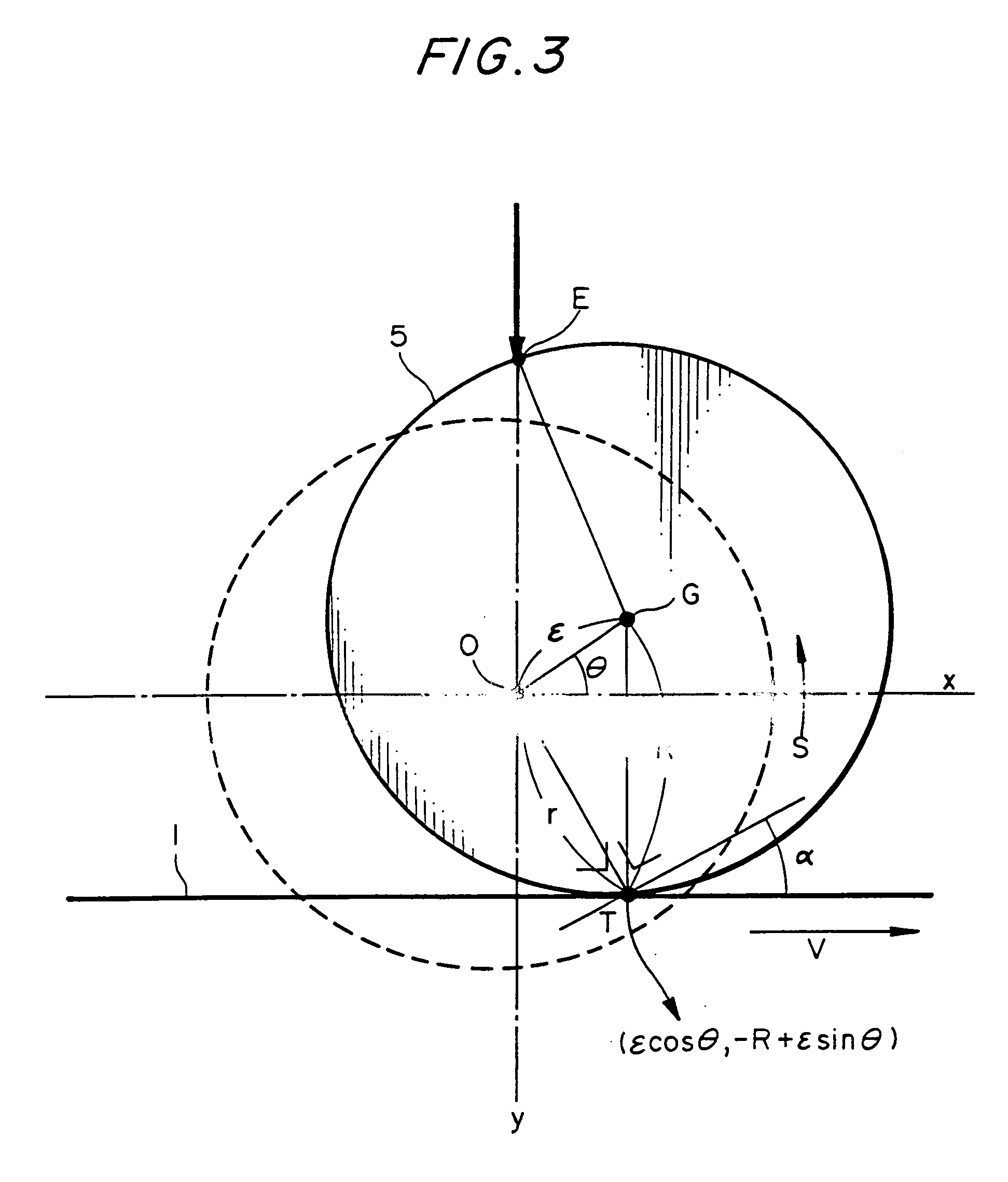
The eccentricity of the shaft causes the angular velocity of the drum to vary and cannot be readily coped with by conventional technologies when high resolution is required.
However, the prior art copier of the type using press rollers renders an image irregular in density due to the eccentricity of the drum.
However, if the eccentricity is great and if the drums differ from each other in the phase of eccentricity, then the belt slackens with the result that the belt and each drum slip on each other.
Then, there arise other problems including the variation of transmission speed ascribable to the eccentricity of the gears or rollers (or pulleys) holding the belt, oscillation ascribable to the gears meshing with each other, and the deterioration of the rigidity of the belt.
Although this kind of scheme reduces high-frequency oscillation ascribable to, e.g., the gears, it cannot reduce speed variation ascribable to the eccentricity of the gears or effect accurate control due to the deterioration of the rigidity of the driveline.
The conventional arrangement is susceptible to extraneous oscillation because, considering the torsional oscillation of the drive shaft which is low in rigidity, the gain of a control system cannot be increased.
In the embodiment in which the motor is accommodated in the drive roller, heat is transferred to the belt and lowers image quality.
Further, the motor accommodated in the elongate drive roller makes production difficult and increases the cost.

Method used


Image

  • Device for driving an endless belt and image forming apparatus using the same
  • Device for driving an endless belt and image forming apparatus using the same
  • Device for driving an endless belt and image forming apparatus using the same

Examples


Embodiment Construction

[0054] To better understand the present invention, reference will be made to a specific, tandem image forming apparatus to which the present invention is applied. The image forming apparatus to be described is of the type including an endless belt for conveying a sheet while being pressed against photoconductive drums, and causing the surface of the belt and the surfaces of the drums contacting each other to move without any slip. The endless belt may be replaced with an intermediate image transfer belt, if desired.

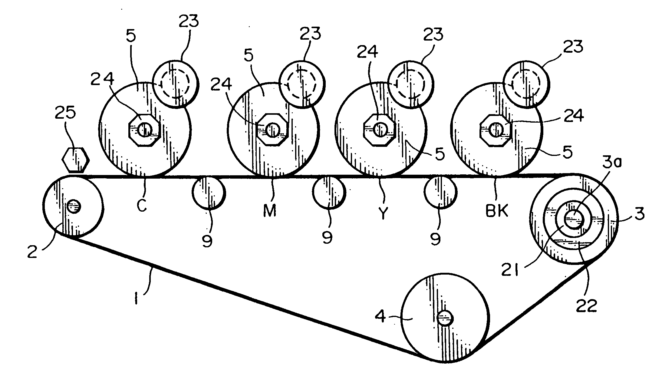
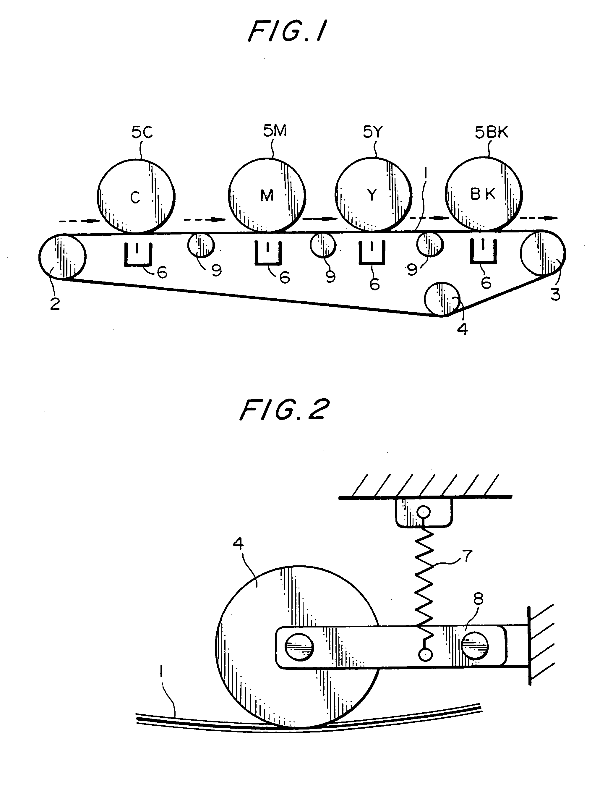
[0055] Referring to FIG. 1 of the drawings, a conveying section included in the image forming apparatus is shown. As shown, an endless belt 1 is passed over a drive roller 3, a driven roller, and a tension roller 4. Four photoconductive drums 5C, 5M, 5Y and 5BK each face a particular charger 6 with the intermediary of the belt 1. The drums 5C, 5M, 5Y and 5BK are assigned to cyan (C), magenta (M), yellow (Y), and black (BK). The chargers 6 are implemented by corona charge...


PUM


Abstract

A device for driving an endless belt of the present invention includes a drive roller and a roller pair adjoining the drive roller at a side where a photoconductive element is positioned and contacting the belt. The eccentricity of the drive roller and that of the roller pair are reduced to reduce the variation of belt speed when the drive roller is controlled at a preselected angular velocity. Even when the drum is eccentric, the device stably operates integrally with the belt without any slip or oscillation.

Description

BACKGROUND OF THE INVENTION [0001] 1. Field of the Invention [0002] The present invention relates to a device for driving an endless belt with belt driving means and rotary bodies arranged side by side in the direction of movement of the belt and driven by the belt. Also, the present invention relates to a color copier, color laser printer or similar color image forming apparatus including belt driving means for moving an intermediate image transfer belt or a sheet conveying belt, and photoconductive drums arranged side by side in the direction of movement of the belt and driven by the belt. [0003] 2. Description of the Background Art [0004] Today, an ink jet printing system and an electrophotographic printing system are extensively applied to a low-speed and a medium or high speed color image forming apparatus, respectively. Particularly, high-speed color image forming apparatuses included a tandem color copier. [0005] Japanese Patent Laid-Open Publication Nos. 10-246995 and 63-813...

Claims


Application Information

Patent Timeline
Patent Type & Authority Applications(United States)
IPC IPC(8): B41J11/00G03G15/16B65H5/02F16H7/12G03G15/00H02P6/10H04N1/047H04N1/12
CPCB41J11/007H04N1/0473H04N1/12H04N2201/0458H04N2201/04772H04N2201/04722H04N2201/04732
Inventor KOIDE, HIROSHI
Owner KOIDE HIROSHI
Learn More