
Method for establishing a radio channel in a wireless cdma network wherein the preamble signal increases in power during transmission

Inactive Publication Date: 2005-10-06
TELEFON AB LM ERICSSON (PUBL)
View PDF7 Cites 77 Cited by
  • Summary
  • Abstract
  • Description
  • Claims
  • Application Information

AI Technical Summary

Benefits of technology

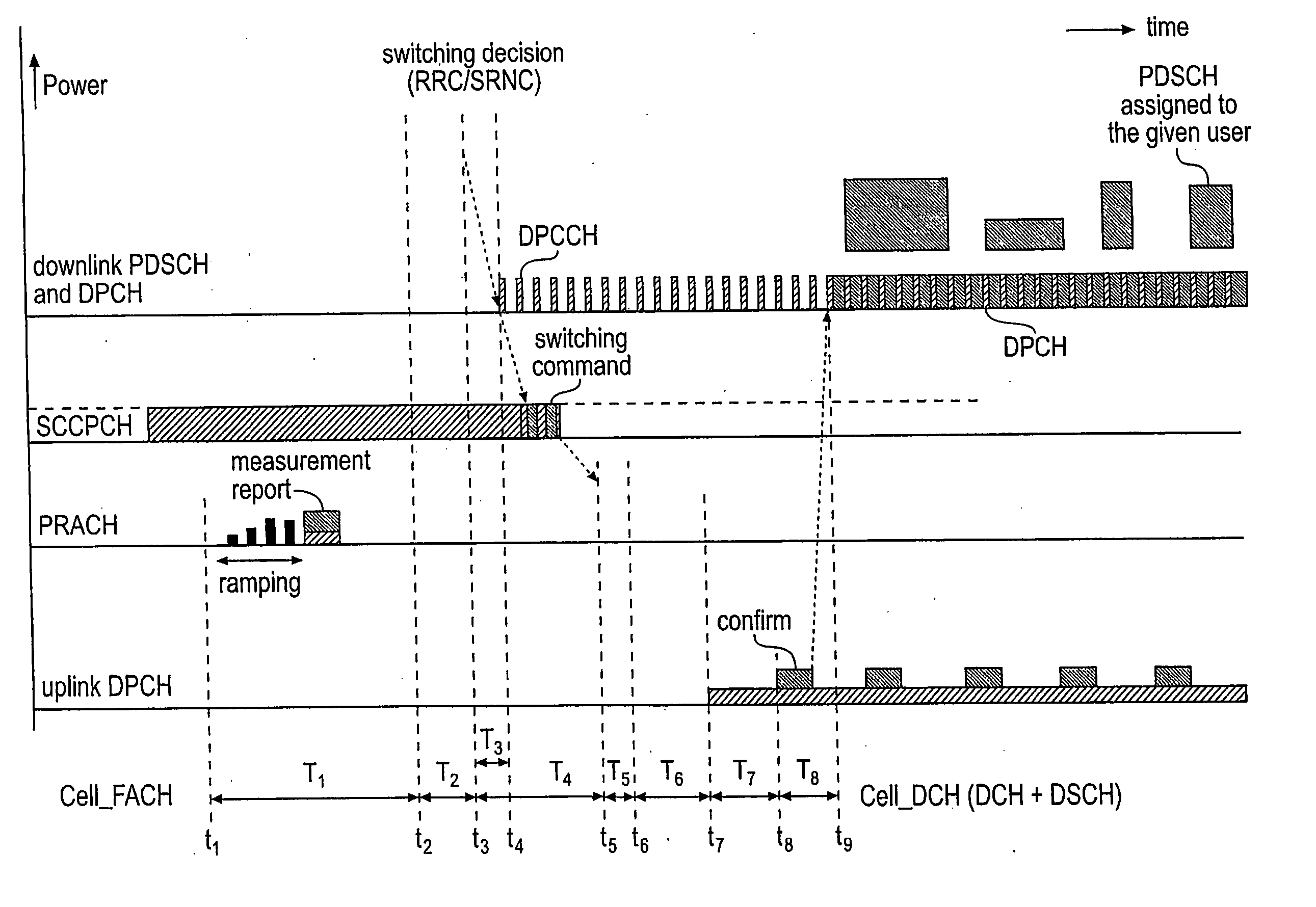
[0016] In the synchronization scheme according to the invention, when a user device (or user equipment, UE) such as a mobile terminal is establishing a channel with a network, the user device transmits signals on the uplink DPCCH, and the power of these signals is ramped up from a calculated initial power level until the transmission is detected by the receiver, i.e. until the receiver has obtained synchronization to the uplink signal. It is presumed that the receiver knows the spreading code used by the sender, and furthermore the receiver is aware that the sender is trying to establish a link within a well-defined time window. Furthermore, since a dedicated spreading code is employed, it is used by only a single transmitter. There is no contention and therefore no possibility for collisions due to the spreading code. This simplifies the detection task of the receiver.
[0020] This means that the scheme according to the present invention can achieve very power efficient, highly secure-detection of the DPCCH transmission in the base station receiver.

Problems solved by technology

A major challenge in mobile communication systems is to perform efficient data transmission at low terminal power consumption.
Packet data transmission services in particular are characterized by extreme burstiness of the traffic volume that needs to be transferred over the radio interface with one user.
If the physical link between a terminal and the network is maintained continuously, even when no user data actually needs to be transmitted, this leads to continuous power consumption of the terminal.
A potential problem with this approach is the need to perform a new link synchronization before each transmission on a common channel, and whenever transmission on a dedicated channel needs to be started again.

Method used


Image

  • Method for establishing a radio channel in a wireless cdma network wherein the preamble signal increases in power during transmission
  • Method for establishing a radio channel in a wireless cdma network wherein the preamble signal increases in power during transmission
  • Method for establishing a radio channel in a wireless cdma network wherein the preamble signal increases in power during transmission

Examples


Embodiment Construction

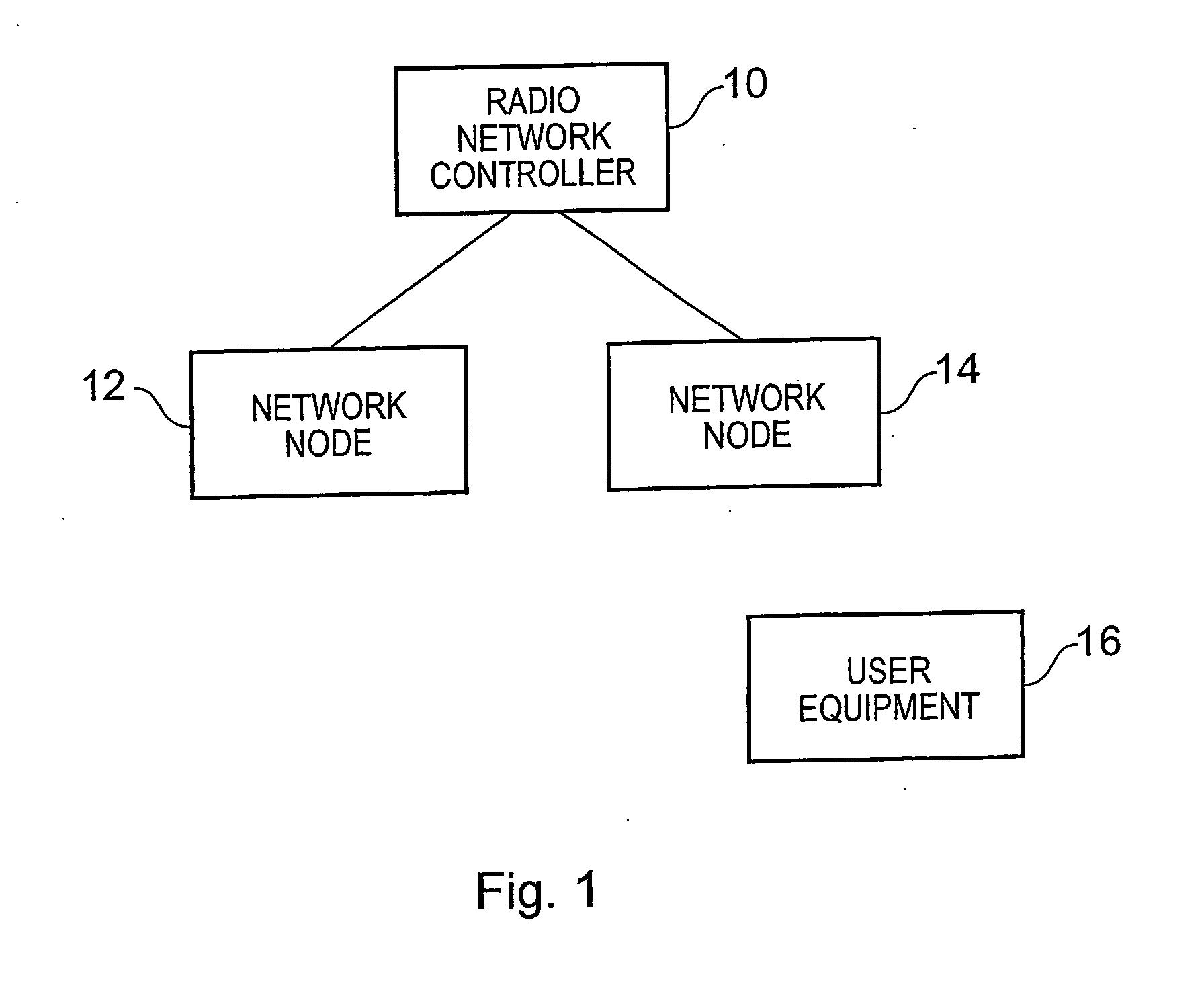
[0049]FIG. 1 shows a small part of a radio communications network operating in accordance with the present invention. Thus, FIG. 1 shows a radio network controller 10, which serves network nodes 12, 14 which are located in respective cells of the system. In the illustrated embodiment of the invention, the system is a digital wideband code division multiple access (WCDMA) wireless communications network, for example a UMTS network.

[0050] In particular, the network node includes an uplink signal power detector, which is based on peak detection in long-term delay power spectrum (LT-DPS) estimations, which for instance can be calculated with a matched filter.

[0051]FIG. 1 also shows a user equipment 16, which may for example be a mobile phone, or any other device which can establish a connection to the network.

[0052] The network nodes 12, 14 and user equipment 16, are generally conventional, in the sense that they comply with existing versions of the UMTS standards. They will therefor...


PUM


Abstract

In a synchronization scheme, for example for establishing a channel in a UMTS radio communication system, when a user device (or user equipment, UE) such as a mobile terminal is establishing a channel with a network, the user device transmits signals on the uplink DPCCH, and the power of these signals is ramped up from a calculated initial power level until the transmission is detected by the receiver, i.e. until the receiver has obtained synchronization to the uplink signal.

Description

TECHNICAL FIELD OF THE INVENTION [0001] This invention relates to a method of establishing a radio communication channel, in particular between a mobile station and a network. BACKGROUND OF THE INVENTION [0002] A major challenge in mobile communication systems is to perform efficient data transmission at low terminal power consumption. Packet data transmission services in particular are characterized by extreme burstiness of the traffic volume that needs to be transferred over the radio interface with one user. Time intervals where large amounts of traffic need to be transmitted alternate with time intervals where there is only a very low volume traffic or no traffic at all. [0003] This is relevant in the case of UMTS, and the invention will be described with reference to its use in a Wideband Code Division Multiple Access (WCDMA) wireless network, although it will be appreciated that the same principle may be applied in other networks. [0004] If the physical link between a terminal...

Claims


Application Information

Patent Timeline
IPC IPC(8): H04B7/005H04W52/50H04W52/58
CPCH04W52/50H04W52/58
Inventor GRANZOW, WOLFGANGFRANK, GEORGGERSTENBERGER, DIRK
Owner TELEFON AB LM ERICSSON (PUBL)
Learn More