Motor with improved rotary shaft supporting structure

a technology of supporting structure and rotary shaft, which is applied in the direction of horology, magnetic circuit shape/form/construction, instruments, etc., can solve the problems of adhesion and other problems, and achieve the effects of high positional precision, high precision and simple structur

Inactive Publication Date: 2005-10-13
SANKYO SEIKI MFG CO LTD
View PDF7 Cites 6 Cited by
  • Summary
  • Abstract
  • Description
  • Claims
  • Application Information

AI Technical Summary

Benefits of technology

[0014] According to the present invention, while the engaging sections of the bearing plate hook onto the end surface of the stator core at one end section in the motor axial line direction of the stator, the first convex sections of the bearing plate are gripped between the end surface of the stator core and the end plate within the concave sections that are formed between the bent parts of the salient poles in the stator core. For this reason, the bearing plate is bound by the end plate via the first convex sections towards the outside (i.e., the side opposite to the side where the rotor is positioned) in the motor axial line direction and bound by the stator core towards the inside (i.e., the side where the rotor is positioned) in the motor axial line direction. Consequently, although the structure is simple, the bearing plate is firmly fixed to the end section of the stator. As a result, there is no need to employ a structure in which a bearing protrudes significantly from an end plate in order to firmly fix the bearing to the end plate, and the motor can therefore be made thinner. Furthermore, when assembling the motor, after the bearing plate is interposed between the stator core and the end plate, only a single process of fixing the end plate to the stator core through welding, caulking or adhesion is required. Consequently, there is no need to perform time-consuming processes such as fixing the bearing plate to the end plate through such methods as welding, caulking, or adhesion, and then fixing the end plate to the stator core through such methods as welding, caulking or adhesion again.
[0015] According to the present invention, the bearing plate may preferably hold the bearing in its center position and tip end parts of the first convex sections may preferably abut inner ends of the concave sections. With this structure, the stator core and the bearing plate can be positioned directly. Furthermore, since the concave sections can be formed on the stator core with high positional precision through press machining, once the bearing plate is positioned using the concave sections as a reference, centering of the bearing can be done with high precision.
[0016] According to the present invention, the engaging sections may preferably be formed as second convex sections that protrude towards the outer circumference side from the bearing plate, and notches in which to mount the second concave sections may preferably be formed in the end plate at the circumferential edge of a hole where the bearing plate is placed. In other words, by forming the notches, in which are mounted the engaging sections of the bearing plate, in the end plate, the engaging sections of the bearing plate do not overlap the end plate in the motor axial line direction; makes it a possible to make the motor even thinner by at least the thickness of the engaging sections.

Problems solved by technology

Furthermore, when assembling the motor, after the bearing plate is interposed between the stator core and the end plate, only a single process of fixing the end plate to the stator core through welding, caulking or adhesion is required.

Method used


Image

  • Motor with improved rotary shaft supporting structure
  • Motor with improved rotary shaft supporting structure
  • Motor with improved rotary shaft supporting structure

Examples


first embodiment

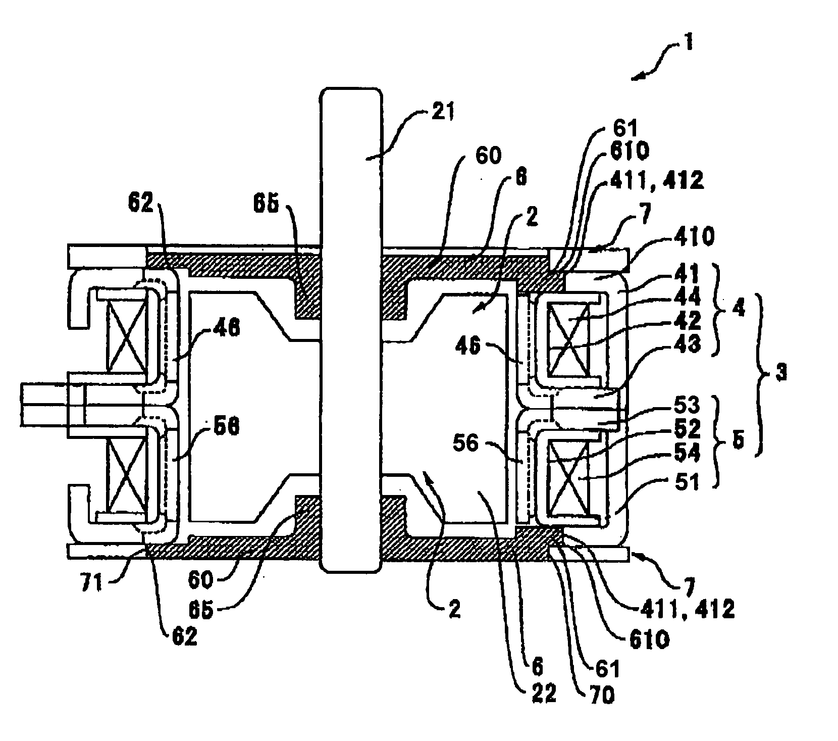
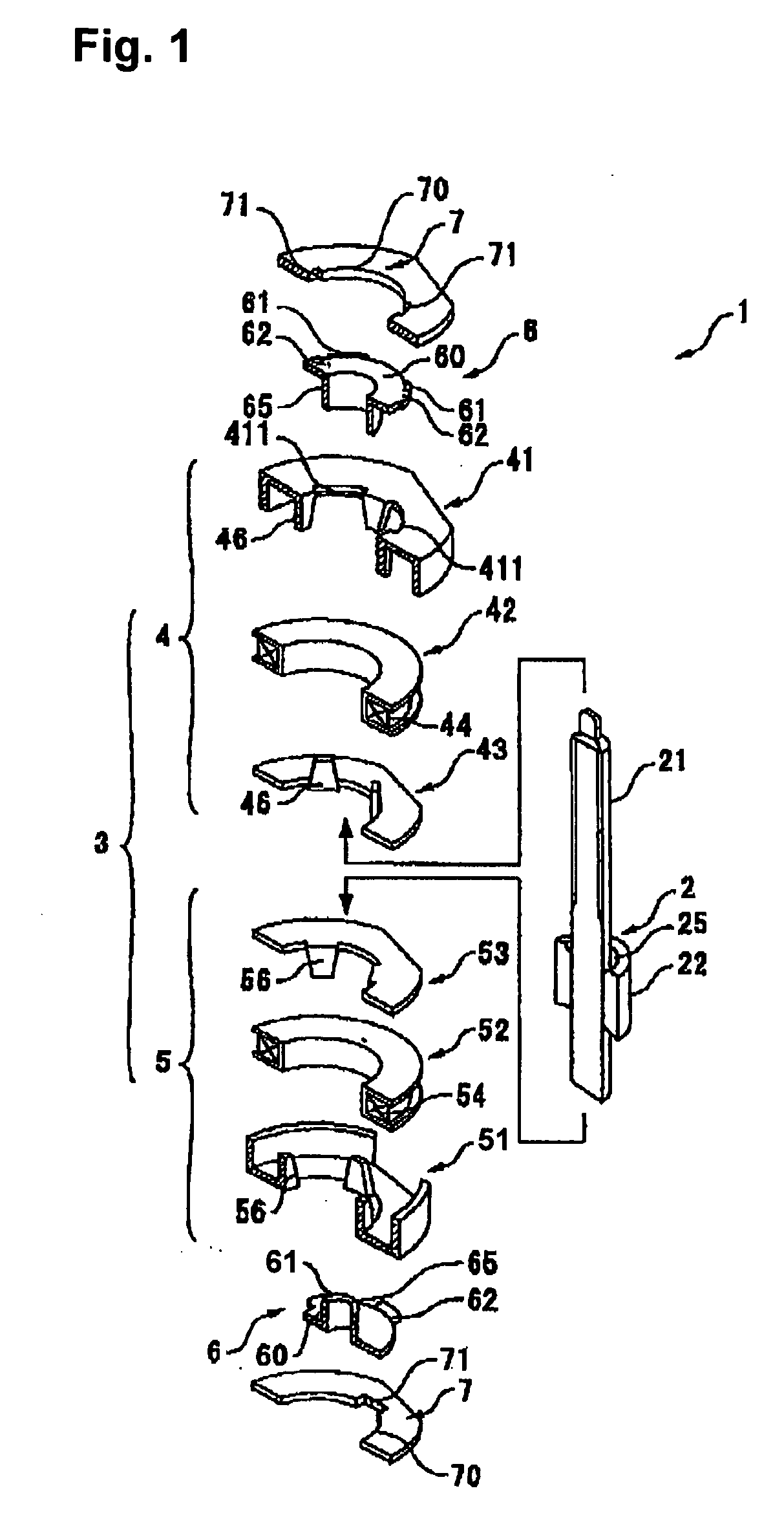
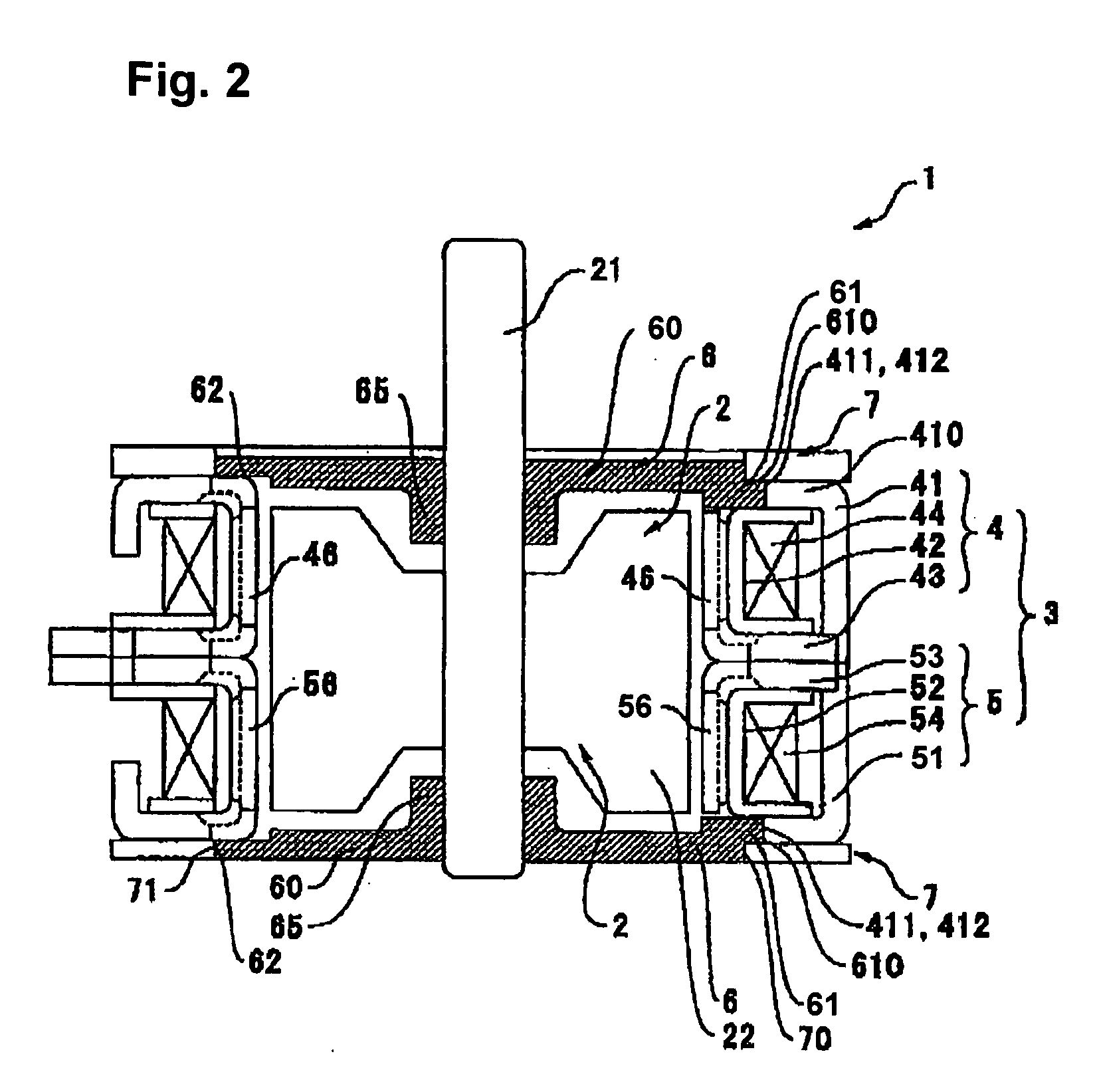
[0035]FIGS. 1 and 2 are an exploded perspective view and a longitudinal cross-sectional view, respectively, of a motor according to the first embodiment of the present invention. FIGS. 3(a)-(i) are a plan view, a cross-sectional view and a bottom view of an end plate; a plan view, a cross-sectional view and a bottom view of a bearing plate; and a plan view, a cross-sectional view and a bottom view of a first outer stator core, all used in the motor shown in FIGS. 1 and 2, respectively. FIGS. 4(a)-(f) are a plan view, a cross-sectional view and a bottom view of a state in which the end plate and the bearing plate shown in FIG. 3 are placed together, and a plan view, a cross-sectional view and a bottom view of a state in which the end plate and the bearing plate are mounted on the first outer stator core, respectively.

[0036] As shown in FIGS. 1 and 2, a stepping motor 1 according to the present embodiment is a PM-type stepping motor and comprises a rotor 2 with a permanent magnet 22,...

second embodiment

[0055]FIG. 5 is a longitudinal cross-sectional view of a motor in accordance with a second embodiment of the present invention. FIGS. 6(a)-(i) are a plan view, a cross-sectional view and a bottom view of a second outer stator core; a plan view, a cross-sectional view and a bottom view of a bearing plate; and a plan view, a cross-sectional view and a bottom view of an end plate, respectively, all used in the motor shown in FIG. 5. FIGS. 7(a)-(f) are a plan view, a cross-sectional view and a bottom view of a state in which the end plate and the bearing plate shown in FIG. 6 are placed together, and a plan view, a cross-sectional view and a bottom view of a state in which the end plate and the bearing plate are mounted on the second outer stator core, respectively.

[0056] As shown in FIG. 5, a stepping motor la according to the present embodiment is a PM-type stepping motor like the motor according to the first embodiment and comprises a rotor 2 with a permanent magnet 22, a rotary sha...

third embodiment

[0070] The present invention is also applicable to a stepping motor having a structure shown in FIGS. 8 and 9 among stepping motors whose rotary shaft has a cantilevered structure.

[0071] FIGS. 8(a) and (b) are a longitudinal cross-sectional view of a motor in accordance with another embodiment of the present invention and an exploded cross-sectional view of a part of the motor, respectively. FIGS. 9(a)-(h) are a side view of a rotor, a side view of a steel ball, a plan view of a slide bearing (a bearing member), a bottom view of an outer stator core placed opposite to an output end, a plan view of a bearing plate holding the bearing member, a bottom view of the slide bearing, a bottom view of the bearing plate, and a bottom view of a leaf spring, respectively, all used in the motor shown in FIG. 8.

[0072] In FIGS. 8(a) and 8(b) and FIGS. 9(a)-(h), a stepping motor 1b according to the present embodiment includes a rotor 2, a steel ball 262, which is mounted in a concave section 28 f...


PUM


Abstract

A stepping motor includes a rotor with a permanent magnet, a rotary shaft extending from the rotor and a stator placed around the rotor. The stepping motor comprises a stator core placed on one end section in a motor axial line direction of the stator, a bearing plate that includes a bearing for rotatably supporting the rotary shaft and is placed at an end section of the stator adjacent to the stator core, and an end plate fixed to an end surface of the stator core on an outer circumference side of the bearing plate. The stator core includes a plurality of salient poles that bend in the motor axial line direction at an inner circumferential edge of the stator core to oppose the permanent magnet, and concave sections that recede in the radial direction and formed between the bent parts of the salient poles. The end plate is affixed to an end surface of the stator core on an outer circumference side of the bearing plate, wherein the bearing plate has a plurality of engaging sections that hook on the end surface of the stator core and a plurality of convex sections that protrude towards inside of the concave sections of the stator core and hook on an end surface of the end plate.

Description

BACKGROUND OF THE INVENTION [0001] 1. Field of the Invention [0002] The present invention relates to a motor with a stator core whose salient poles bend at the inner circumferential edge in the motor axial line direction. More specifically, the present invention relates to a support structure for supporting a rotary shaft of a motor having such a structure. [0003] 2. Related Background Art [0004] A PM-type stepping motor generally comprises, as shown in FIG. 10(a), a rotor 120 having a permanent magnet 122, a rotary shaft 121 that extends from the rotor 120, and a stator 130 placed to surround the rotor 120. [0005] The stator 130 comprises a first bobbin 142 with a coil wound thereon, and a first outer stator core 141 and a first inner stator core 143, which are placed to interpose the first bobbin 142 from its top and bottom, as well as a second bobbin 152 with a coil wound thereon, and a second inner stator core 153 and a second outer stator core 151, which are placed to interpose...

Claims


Application Information

Patent Timeline
Patent Type & Authority Applications(United States)
IPC IPC(8): H02K37/14H02K37/00H02K1/14H02K5/167H02K5/16
CPCH02K1/145H02K5/1672H02K37/14
Inventor MAYUMI, EIJI
Owner SANKYO SEIKI MFG CO LTD
Why Eureka
Try Eureka