
Piezoelectric devices and methods and circuits for driving same

Inactive Publication Date: 2005-10-13
PAR TECH
View PDF48 Cites 58 Cited by
  • Summary
  • Abstract
  • Description
  • Claims
  • Application Information

AI Technical Summary

Benefits of technology

[0016] A drive circuit produces a drive signal for a pump having a piezoelectric actuator, with the piezoelectric actuator forming a part of the drive circuit and serving to shape a waveform of the drive signal. The piezoelectric actuator essentially serves as a charge storage device for a power supply for the drive circuit. The drive circuit comprises a pulse generator which generates digital pulses; a converter circuit which uses the low voltage, long period digital pulses generated by the pulse generator to produce high voltage, shorter period pulses (charge packets); and, the piezoelectric actuator. The piezoelectric actuator, by its capacitive nature, integrates the charge packets to shape the waveform of the drive signal. Thus the shape for the waveform is influenced by the digital pulses produced by the pulse generator and the capacitance of the piezoelectric actuator. The piezoelectric actuator integrates the charge packets to yield a drive field that preferably approximates a sine wave. While the capacitance of the piezoelectric actuator is essentially fixed, by controlling the generator pulses (e.g., varying a pulse width modulation duty cycle) on a pulse by pulse basis, waveforms of arbitrary complexity can be produced. The drive circuit together with the piezoelectric element facilitates the integration of the high frequency charge packets into a lower frequency drive waveform of any desired wave shape.

Problems solved by technology

Despite its overall ingenious and overall beneficial utilization in piezoelectric pumps, some aspects of using a EL lamp driver circuit are problematic.
As a first example problem, the EL lamp driver is limited in that it operates only at a fixed frequency once installed.
As a second example problem, the output wave form of the EL lamp driver circuit is a modified sawtooth which creates audible noise in the piezo even under load (due to the sharp peak on the waveform output by the EL lamp driver circuit).
So when a drive waveform is applied that has frequency content outside of the targeted fundamental drive frequency, that extraneous frequency content adds little to the work output of the piezoelectric element but greatly increases undesirable actuator audible noise.
As a third example problem, the only variable user input to the EL lamp driver circuit is the voltage input (Vin).
As such, the current drive circuits do not have means for accepting external control inputs or monitoring local actuator related parameters.
Given this fact, it is unavoidable that both “sides” of the piezoelectric actuator are subjected to voltage potentials other than system ground.
This cannot be achieved using the EL lamp driver circuitry.

Method used


Image

  • Piezoelectric devices and methods and circuits for driving same
  • Piezoelectric devices and methods and circuits for driving same
  • Piezoelectric devices and methods and circuits for driving same

Examples


Embodiment Construction

of Drive Circuits

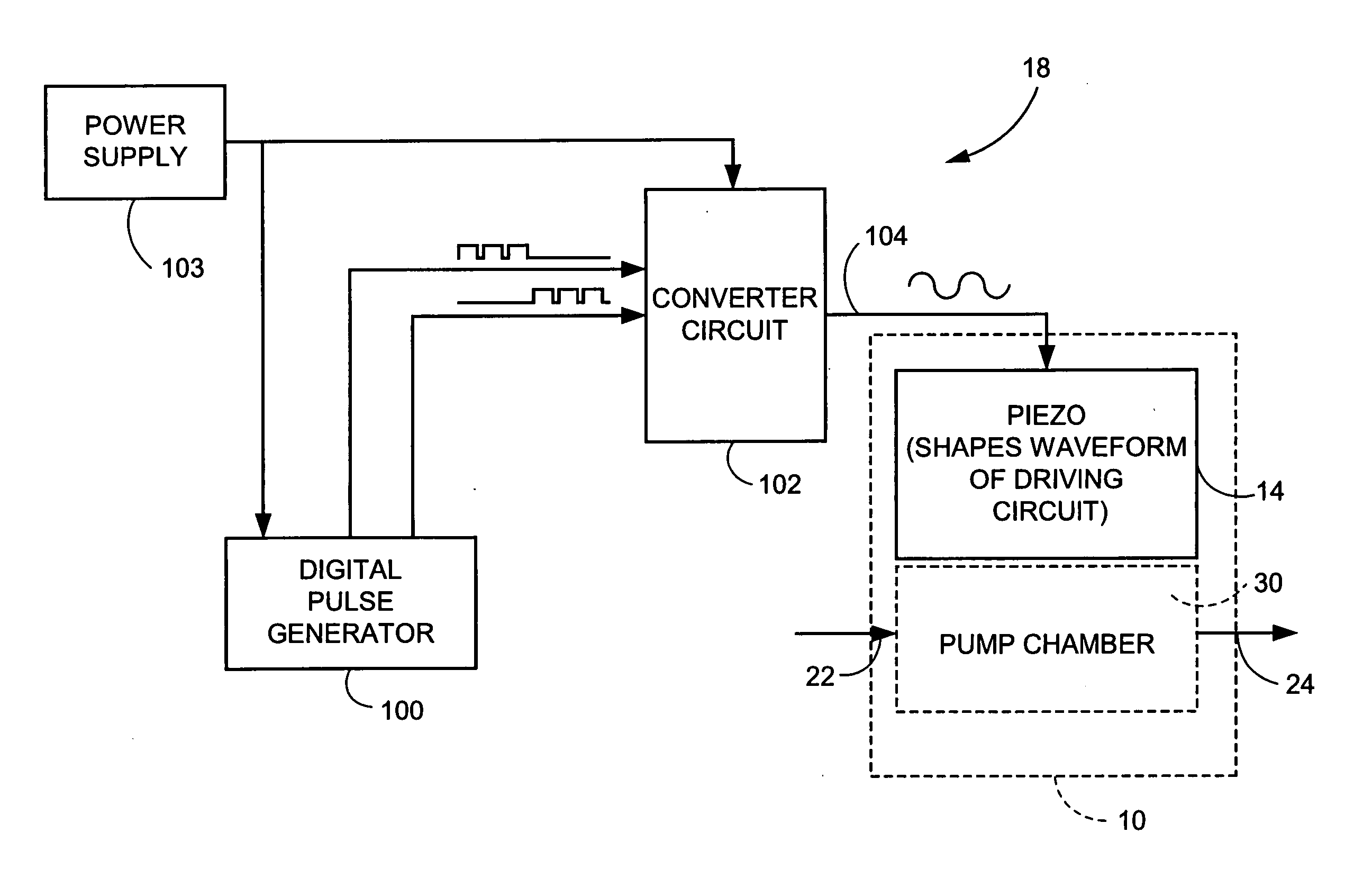
[0059] General non-limiting examples of the piezoelectric actuator drive circuit 18 are illustrated in FIG. 3 and FIG. 3A, FIG. 3B, FIG. 3C, FIG. 3D, FIG. 3E(1), FIG. 3E(2), FIG. 3F, FIG. 3G, FIG. 3H(1), FIG. 3H(2), FIG. 3I(1), FIG. 3I(2), FIG. 3I(3), and FIG. 3J. In each of the example embodiments and modes the piezoelectric actuator drive circuit 18 applies a series of low power, long period digital pulses to the converter circuit 102, so that converter circuit 102 can apply packet charges which are integrated by the piezoelectric actuator 14. In each of these embodiment, the piezoelectric actuator drive circuit 18 applies a drive signal to the piezoelectric actuator 14, with the piezoelectric actuator 14 comprising or being adjacent or proximate to a utilization device. The particular utilization device which uses or incorporates the piezoelectric actuator 14 depends upon the application and / or environment. One example, non-limiting utilization device discussed h...


PUM


Abstract

A drive circuit (18) produces a drive signal for a pump (10) having a piezoelectric actuator (14), with the piezoelectric actuator (14) forming a part of the drive circuit (18) and serving to shape a waveform of the drive signal. The drive circuit (18) comprises a pulse generator (100) which generates pulses; a converter circuit (102) which receives the pulses and produces charge packets at a rate which equals a desired drive frequency; and, the piezoelectric actuator (14). The piezoelectric actuator (14) receives the charge packets and, by its capacitive nature, integrates the charge packets to shape the waveform of the drive signal. Preferably, the piezoelectric actuator (14) integrates the charge packets to yield a drive field that approximates a sine wave. In one non-limiting example embodiment, the pulse generator (100) comprises a microcontroller-based pulsed width modulator (PWM) circuit (116) and the converter circuit (102) comprises a flyback circuit.

Description

[0001] This application is related to the following simultaneously-filed United States patent applications: U.S. patent application Ser. No. 10 / ______ (attorney docket: 4209-37) entitled “Piezoelectric Devices And Methods And Circuits For Driving Same”; U.S. patent application Ser. No. 10 / ______ (attorney docket: 4209-41) entitled “Piezoelectric Devices And Methods And Circuits For Driving Same”; and, U.S. patent application Ser. No. 10 / ______ (attorney docket: 4209-46) entitled “Piezoelectric Devices And Methods And Circuits For Driving Same”; all of which are incorporated by reference herein in their entirety.BACKGROUND [0002] 1. Field of the Invention [0003] This invention pertains to piezoelectric elements, and particularly to circuits and methods for driving piezoelectric elements utilized in such devices such as pumps, for example. [0004] 2. Related Art and Other Considerations [0005] A piezoelectric element is a crystalline material which produces an electric voltage when sub...

Claims


Application Information

Patent Timeline
IPC IPC(8): F04B43/04H01L41/04H01L41/09
CPCF04B43/046H01L41/042H10N30/802
Inventor VOGELEY, JAMESSCHEMMANN, MARCELL F.C.JONES, GARIH S.
Owner PAR TECH
Features
  • Generate Ideas
  • Intellectual Property
  • Life Sciences
  • Materials
  • Tech Scout
  • Unparalleled Data Quality
  • Higher Quality Content
  • 60% Fewer Hallucinations
Learn More