Antenna for portable cellular telephone

Inactive Publication Date: 2005-10-13
PANASONIC CORP
View PDF5 Cites 16 Cited by
  • Summary
  • Abstract
  • Description
  • Claims
  • Application Information

AI Technical Summary

Benefits of technology

[0021] This structure allows shortening of the length of the antenna element, further downsizing and slimming the b

Problems solved by technology

In the conventional antenna for portable cellular telephone, however, resonance frequencies in two significantly different ranges cannot readily be independently an

Method used


Image

  • Antenna for portable cellular telephone
  • Antenna for portable cellular telephone
  • Antenna for portable cellular telephone

Examples


embodiment

PREFERRED EMBODIMENT

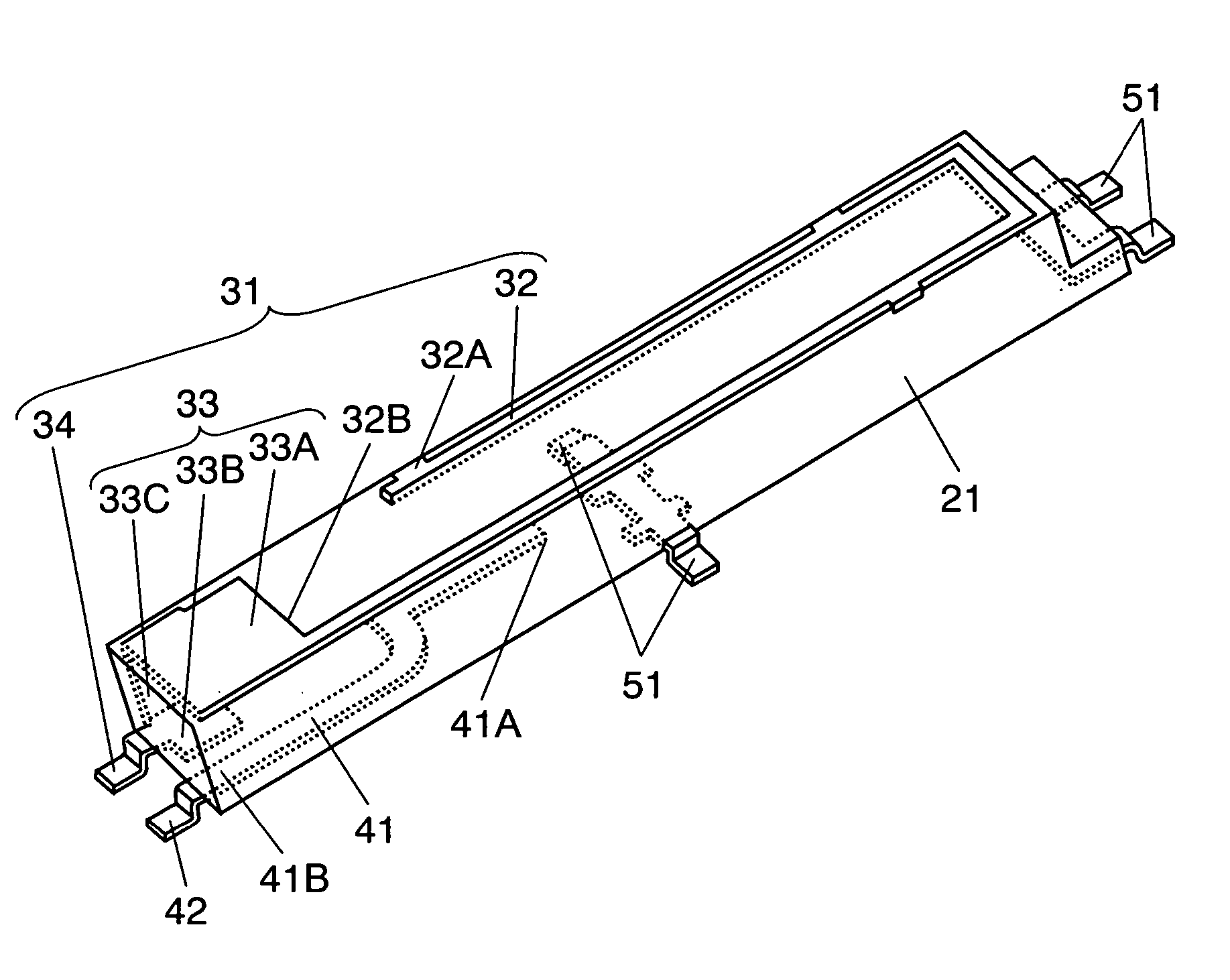
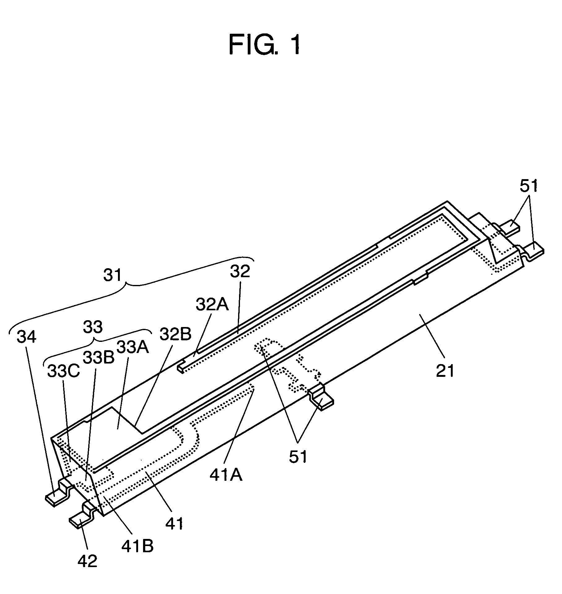
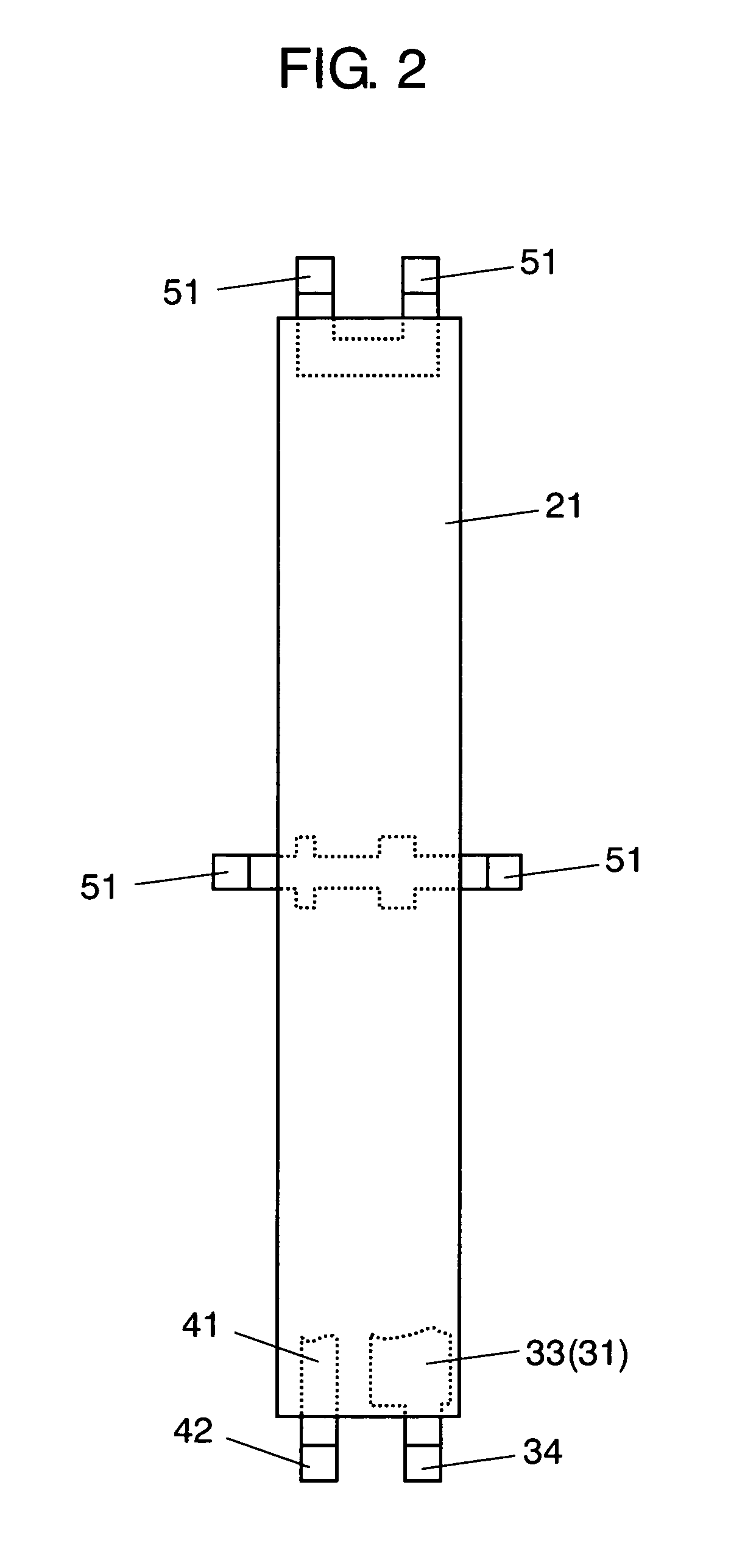
[0035]FIG. 1 is a perspective view of the appearance of an antenna for portable cellular telephone in accordance with an exemplary embodiment of the present invention, and FIG. 2 is a bottom view of the antenna.

[0036] In FIGS. 1 and 2, base 21, of a size that can be housed inside the portable transceiver, is made of heat-resistive resin suitable for surface mounting such as polyphthalamide (PPA). The dielectric constant of base 21 is approximately 4. The use of a material with a higher dielectric constant allows a lower resonance frequency or a smaller antenna. On the other hand, a higher dielectric constant causes a larger dielectric loss, resulting in degradation of antenna radiation characteristics.

[0037] Base 21 is an approximately rectangular parallelepiped, and first antenna element 31 and second antenna element 41 made of a thin metal sheet are anchored to base 21 by insert molding.

[0038] As shown in FIG. 1, first antenna element 31 includes strip 32 an...


PUM


Abstract

An antenna for portable cellular telephone can adjust each of multiple antenna elements efficiently and independently to a predetermined resonance frequency. A first antenna element and second antenna element are mounted on and anchored to one common base. Terminals for feeding power to the first antenna element and the second antenna element are provided respectively. The terminals are coupled to matching circuits. This structure facilitates separate and efficient adjustment of resonance frequency of the first antenna element and the second antenna element.

Description

FIELD OF THE INVENTION [0001] The present invention relates to antennas for portable transceiver, typically mobile phones. BACKGROUND ART [0002] Portable transceiver are becoming ever smaller and lighter. Mobile phones, which are typical wireless terminals subject to this trend, offer a widening range of services for data communications, such as text and video transmissions, in addition to voice communications. Accordingly, the performance of the antenna, which is used for transmitting and receiving radio waves, and inputting and outputting signals, is one factor affecting the performance of mobile phones. [0003] In the field of mobile phones, a single antenna that can receive and transmit signals via multiple radio frequencies at high sensitivity is highly demanded. [0004] A conventional antenna for portable cellular telephone installed in a mobile phone is described next with reference to FIG. 9. [0005]FIG. 9 is a schematic view of the mobile phone in which the conventional antenn...

Claims


Application Information

Patent Timeline
IPC IPC(8): H01Q21/30H01Q1/00H01Q1/24H01Q1/38H01Q5/10H01Q9/30H01Q9/42H01Q21/28H04B1/38
CPCH01Q1/243H01Q1/38H01Q9/30H01Q21/28
Inventor NAKAGAWA, YOSHINOBUSAKO, KOJIYAMABAYASHI, MASAAKIKOSHI, KAZUMINETAKAGI, NAOYUKI
Owner PANASONIC CORP
Why Eureka
Try Eureka