

Receiver circuit comprising equalizer
a technology of equalizer and receiver circuit, which is applied in the direction of amplitude demodulation, line-fault/interference reduction, baseband system details, etc., can solve the problem of insufficient isi compensation for simply providing equalizers with fixed characteristics on the transmission side, and the signal waveform is shorter, so as to suppress intersymbol interference
- Summary
- Abstract
- Description
- Claims
- Application Information
AI Technical Summary
Benefits of technology
Problems solved by technology
Method used
Image

Examples
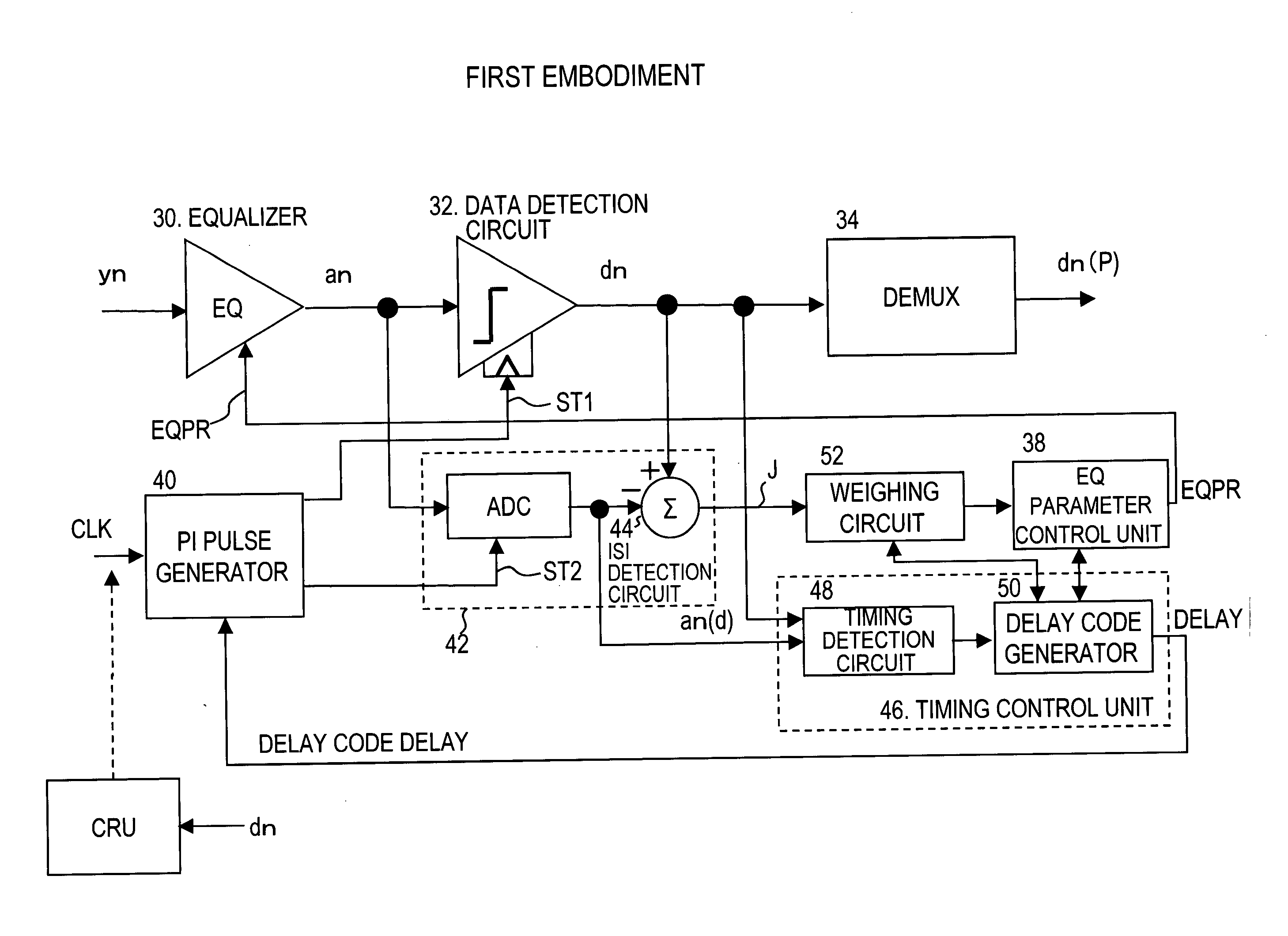
first embodiment
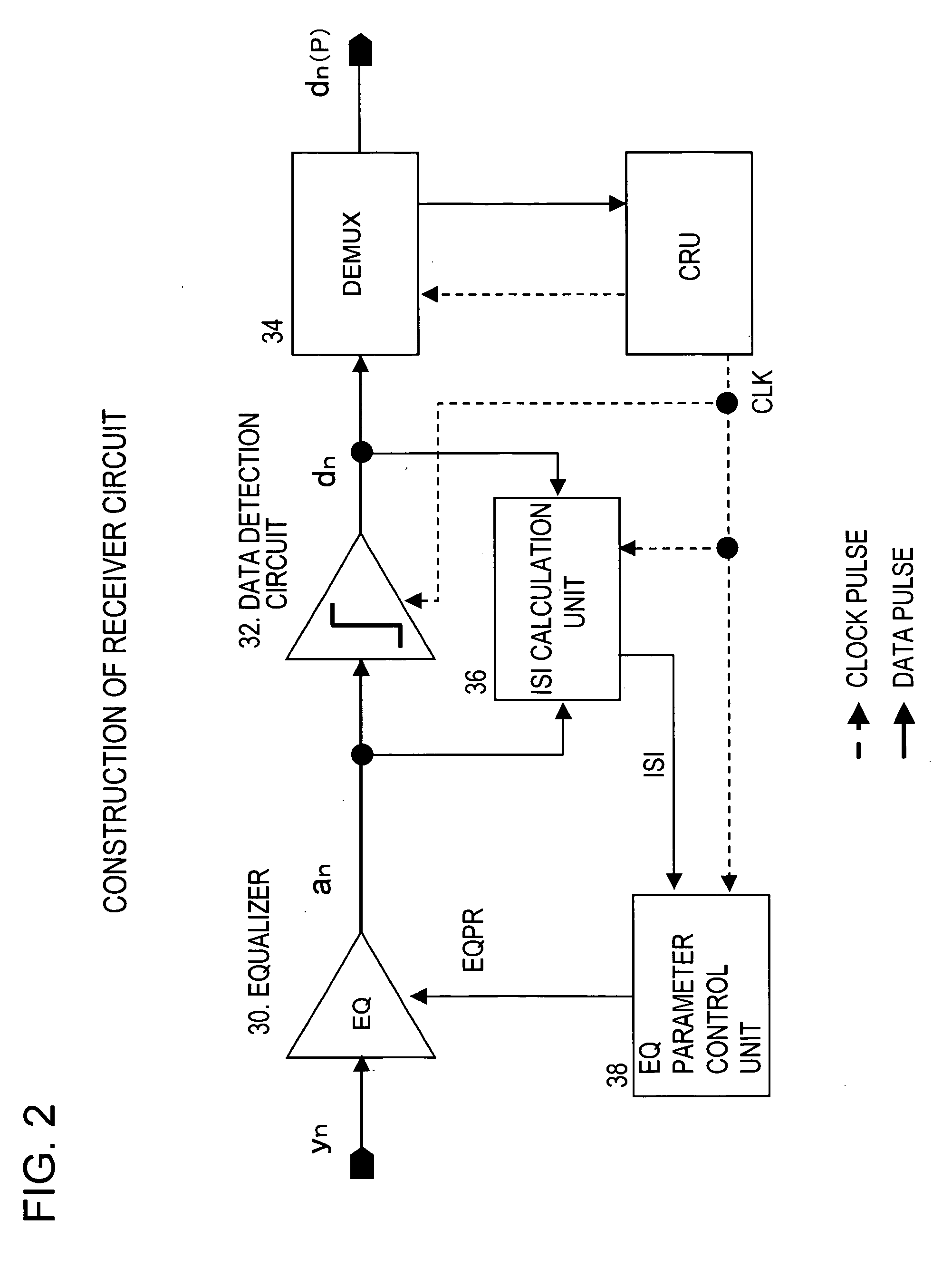
[0045]FIG. 5 is a constitutional view of the receiver circuit of the first embodiment. This receiver circuit comprises an equalizer 30, a data detection circuit 32, a demultiplexer 34, and an equalization parameter control unit 38 that controls the equalization characteristic parameter EQPR of the equalizer. Further, the pulse generation circuit 40, which generates a data sample timing clock ST1 for the detection circuit 32, is provided, and the pulse generation circuit 40 generates the data sample clock ST1 that is controlled at the data center timing DCT of the eye pattern by adding a controlled phase delay to the synchronization clock CLK. The phase delay is set by a delay amount control code DELAY that is generated by a data sample timing control unit 46.
[0046] The ISI detection circuit 42 comprises an analog-to-digital converter ADC that converts the analog output signal an into a digital signal at the timing of the sample timing ST2, and an error generator 44 that generates a...
second embodiment
[0058]FIG. 11 is a constitutional view of the receiver circuit of the second embodiment. In addition to the detection circuit 32, which judges the analog output signal an of the equalizer 30 at the data center timing DCT, this receiver circuit is provided with a detection circuit 33 that judges the analog output signal an at the data boundary timing DBT. Further, an ISI monitor unit 53, which detects the phase fluctuation amount at the data boundary of the analog output signal an of the equalizer 30 as ISI information, is also provided, wherein the equalization parameter control unit 38 determines the equalization parameter to minimize this phase fluctuation amount. Further, the pulse generation circuit 40 generates a data boundary timing clock DBT on the basis of the synchronization clock CLK generated by the clock recovery unit CRU and supplies the data boundary timing clock DBT to the detection circuit 33 as a sample clock. The pulse generation circuit 40 also generates a data ce...
third embodiment
[0071]FIG. 17 shows the receiver circuit of a third embodiment. In the third embodiment, the ISI monitor unit 53 detects the amplitude fluctuation amount dAM of the analog output signal an of the equalizer 30 at the data boundary timing DBT and the equalization parameter control unit 38 controls the characteristic parameter EQPR of the equalizer 30 to reduce the amplitude fluctuation amount dAM.
[0072]FIG. 18 is a theoretical diagram of the third embodiment. FIG. 18A is an eye pattern close to the boundary DBT before equalization of the received signal yn and FIG. 18B is an eye pattern close to the boundary after equalization. Because ISI has not been removed or suppressed from the eye pattern before equalization, the eye pattern at the boundary exhibits phase fluctuations in the temporal direction and amplitude fluctuations dAM in the amplitude direction. In addition, when ISI is suppressed through equalization, the phase fluctuation amount and amplitude fluctuation amount are smal...
PUM
 Abstract
Description
Claims
Application Information