
Portable x-ray fluorescence using machine source

a fluorescence and machine source technology, applied in the field of chemical analysis systems and methods, can solve problems such as limitations and problems of conventional equipment and methods

Inactive Publication Date: 2005-10-13
TROMBKA JACOB I +5
View PDF4 Cites 22 Cited by
  • Summary
  • Abstract
  • Description
  • Claims
  • Application Information

AI Technical Summary

Benefits of technology

[0008] According to another aspect of the present invention, an instrument comprises a housing; a handle; a supply circuit for generating a variable voltage from approximately 10 kv to 60 kv, up to approximately 100 milliamps; an x-ray generator, configured to receive power from the supply circuit, employing a 60 kv excitation voltage, the generator including metal ceramic and end window targets constructed with a target material consistent with non-interference with sample fluorescent x-rays, and a photodiode to excite electron emission from a photoelectric surface; a protect circuit to prevent tube arching, if the current to the photodiode diode shuts off, wherein the perimeter of the housing defines a plane, and the instrument further includes a specimen holder configured to hold a specimen approximately in the plane; a channel opposing the generator, through the plane; and an x-ray detector configured to detect radiation from na and up, the detector including a schottky cadmium zinc element; and a thermoelectric element for cooling the detector.

Problems solved by technology

Such remote locations, however, present certain limitations and problems for conventional equipment and methods.

Method used


Image

  • Portable x-ray fluorescence using machine source
  • Portable x-ray fluorescence using machine source
  • Portable x-ray fluorescence using machine source

Examples


Embodiment Construction

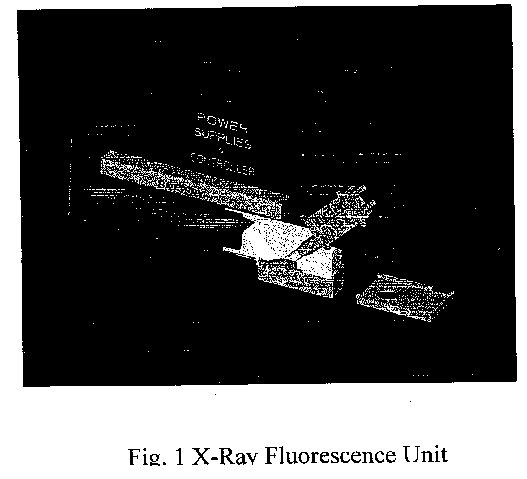
[0014]FIG. 1 shows an exemplary portable x-ray fluorescence (XRF) unit 1 for field use, according to a preferred embodiment of the present invention. Unit 1 is rugged, self-contained, portable, and operates at low power.

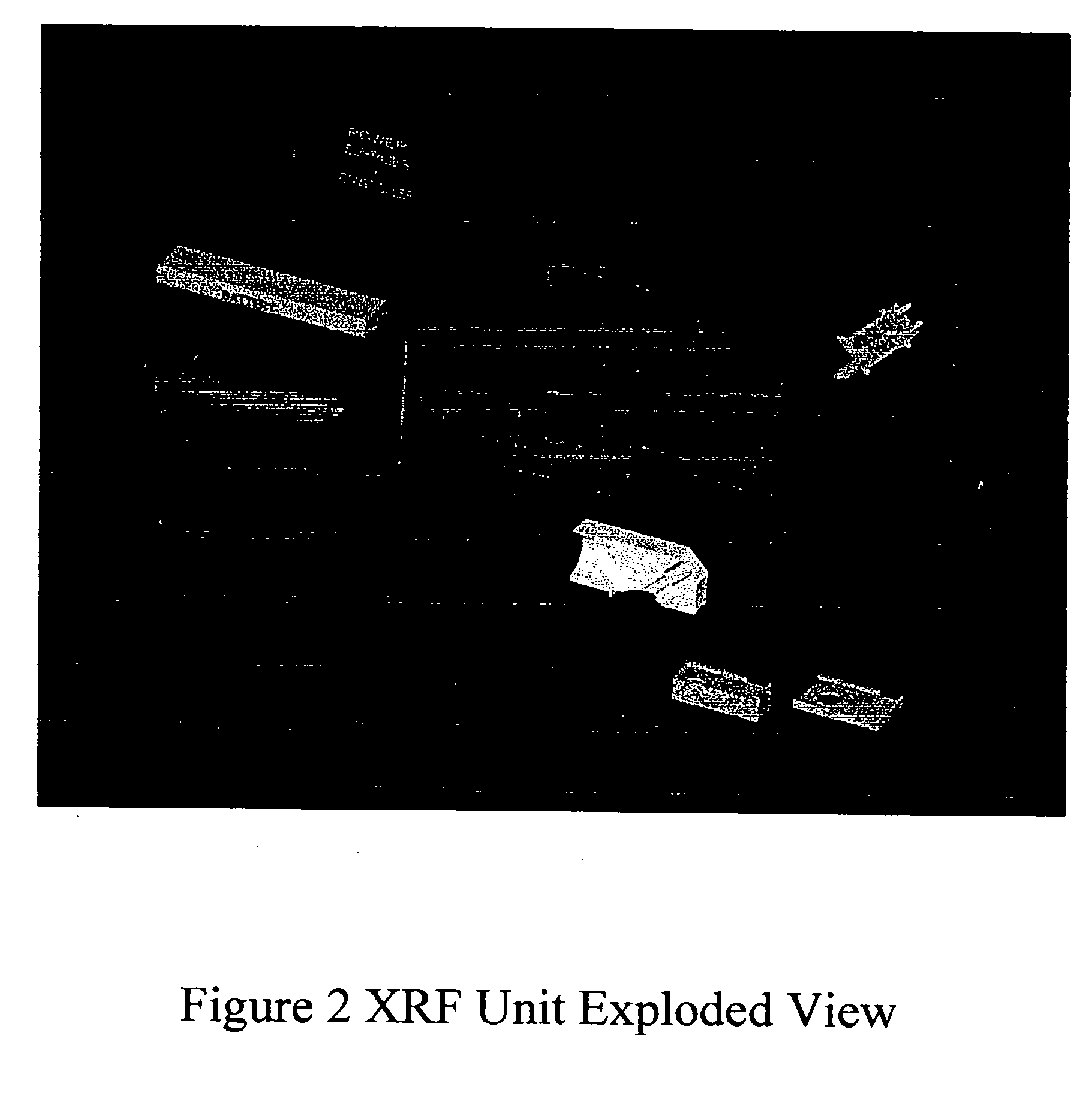
[0015]FIG. 2 is an exploded view corresponding to FIG. 1

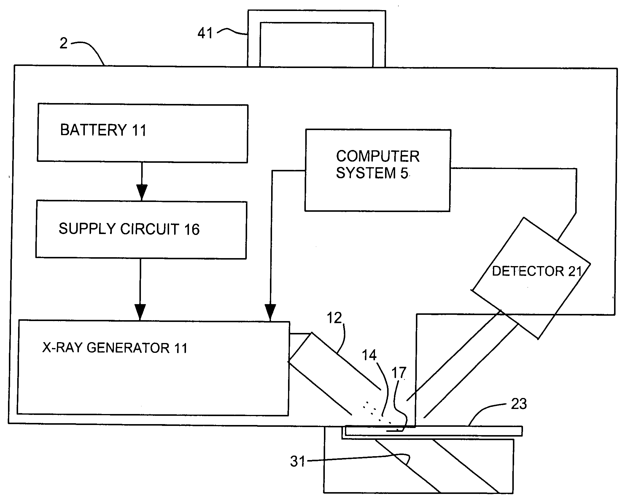
[0016]FIG. 3 is a diagram emphasizing other aspects of the exemplary unit 1. Housing 2, having handle 41, is the size of a briefcase. Handle 41 can support the weight of housing 2 and the elements enclosed by housing 2.

[0017] Unit 1 can measure concentrations of such elements as Ba and Sb (important in the detection of gun powder residue detection) down to milligrams concentrations.

[0018] Battery 11 and voltage step up circuit 16 supply power to x-ray generator 11. X-ray generator 11 operates up to 60 KV and 100 milliamps.

[0019] Digital computer system 5 enables automated calibration, health of the unit, data accumulation, data analysis, data storage, data transmission, and acquisition systems to be integrat...


PUM

PropertyMeasurementUnit
perimeteraaaaaaaaaa
voltageaaaaaaaaaa
currentaaaaaaaaaa

Abstract

Disclosed are systems and systems for in-situ chemical analysis at remote locations.

Description

[0001] This Application claims the benefit of Application Ser. No. 60 / 505,728 filed Sep. 22, 2003 for PORTABLE RUGGED LOW POWERED X-RAY FLUORESCENT USING MACHINE SOURCE, the contents of which are herein incorporated by reference.BACKGROUND OF THE INVENTION [0002] 1. Field of the Invention [0003] This invention relates generally to systems and methods for chemical analysis and, more particularly, to systems and methods employing x-ray fluorescence for chemical analysis. [0004] 2. Description of Related Art [0005] In-situ elemental analysis of materials is useful in diverse applications, such as analysis at forensic sites or on planetary lander missions. Such remote locations, however, present certain limitations and problems for conventional equipment and methods. SUMMARY OF THE INVENTION [0006] It is an object of the present invention to provide systems and methods for in-situ chemical analysis at remote locations. [0007] To achieve this and other objects of the present invention, a...

Claims


Application Information

Patent Timeline
Patent Type & Authority Applications(United States)
IPC IPC(8): G01N23/20G01N23/223G01T1/36
CPCG01N2223/076G01N23/223
Inventor TROMBKA, JACOB I.FLOYD, SAMUEL R.SCHWEITZER, JEFFREYEISEN, YOSSIMCCLANAHAN, TIMOTHY P.RUITBERG, ARTHUR P.
Owner TROMBKA JACOB I
Learn More