Electron collector system

a technology of electron collector and energy management system, which is applied in the direction of x-ray tube details, x-ray tubes, nuclear engineering, etc., can solve the problems of increased heating of x-ray tubes, new constraints and requirements for the functionality of ct imaging systems, and high voltage potential generation of large amount of heat within x-ray tubes

Inactive Publication Date: 2005-10-13
GENERAL ELECTRIC CO
View PDF6 Cites 7 Cited by
  • Summary
  • Abstract
  • Description
  • Claims
  • Application Information

AI Technical Summary

Benefits of technology

[0017] The present invention has several advantages over existing x-ray tube cooling systems. One of several advantages of the present invention is that it provides a path to force the heat flex to flow more closely to the liquid cooled finback area to increase cooling efficiency. Another advantage of the present invention is that it relieves plastic strain on the window attachment.

Problems solved by technology

Although the increase in imaging speed generates improved imaging capability, it causes new constraints and requirements for the functionality of the CT imaging systems.
The high voltage potential generates a large amount of heat within the x-ray tube, especially within the anode.
Additionally, electrons within the electron beam are back-scattered from the anode and impinge on other components within the vacuum vessel, causing additional heating of the x-ray tube.
As a result, the x-ray tube components are subject to high thermal stresses decreasing component life and reliability of the x-ray tube.
High temperatures at an interface between the vacuum vessel and a transmissive window in the casing cause the cooling fluid to boil, which may degrade the performance of the cooling fluid.
Bubbles may form within the fluid and cause high voltage arcing across the fluid, thus degrading the insulating ability of the fluid.
Further, the bubbles may lead to image artifacts, resulting in low quality images.
These approaches, however, are limited with regard to energy storage and dissipation.
Due to inherent poor efficiency of x-ray generation and desire for increased x-ray flux, heat load is increased that must be dissipated.
Bubbles from boiling coolant obscure the window and thereby compromise image quality.
Further boiling of the coolant results in chemical breakdown of the coolant and sludge formation on the window, which also results in poor image quality.
Although, the heat exchange chamber aids in cooling the electron collector, it is difficult to effectively manufacture due to its complexity and large number of seams, which each need to be properly sealed.
Also, the heat exchange chamber has limited effectiveness in cooling of and preventing deposits from forming on the x-ray tube window.
Also, portions of the window have been known to crack due to cyclic thermal loadings.

Method used


Image

  • Electron collector system
  • Electron collector system
  • Electron collector system

Examples


Embodiment Construction

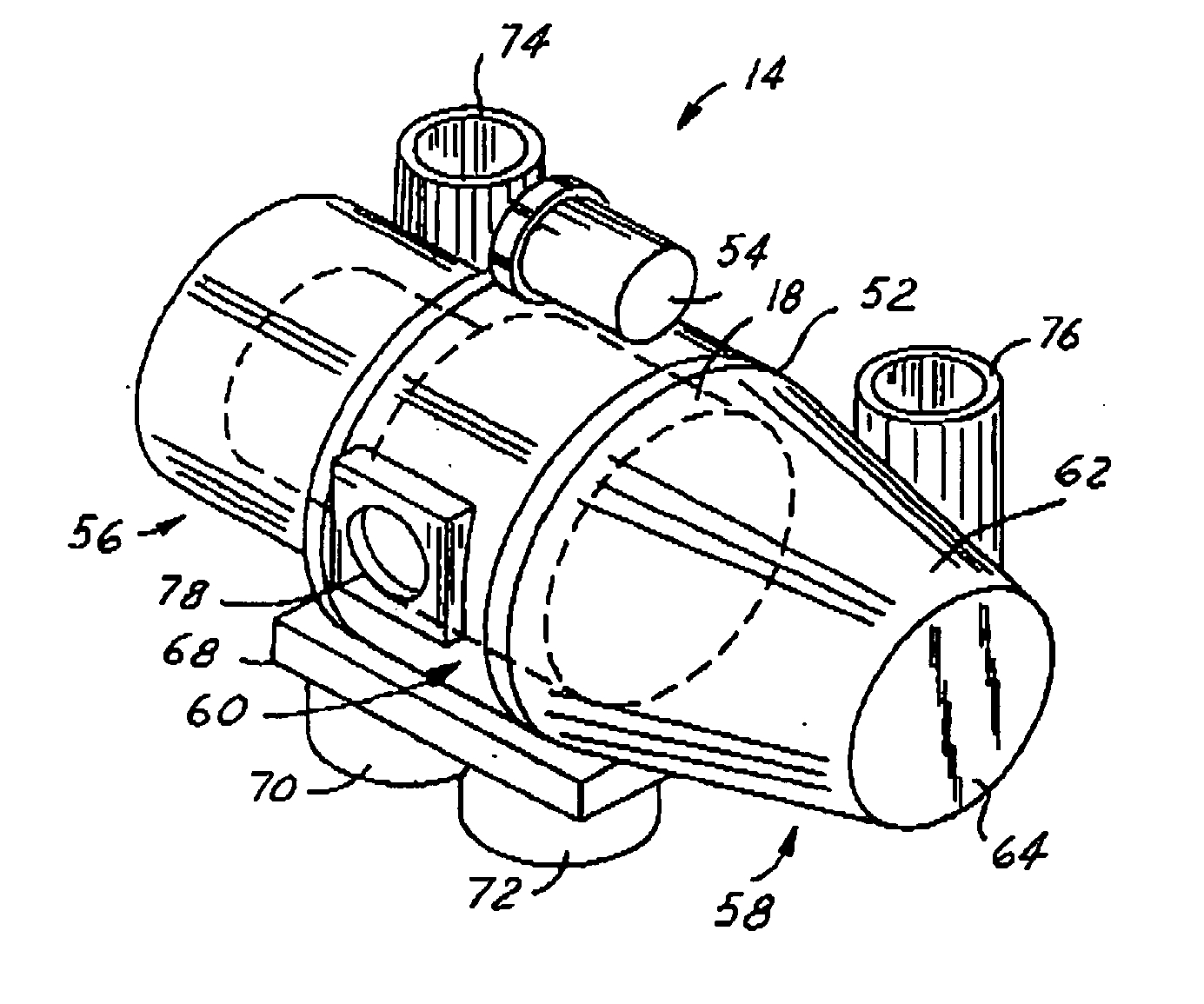
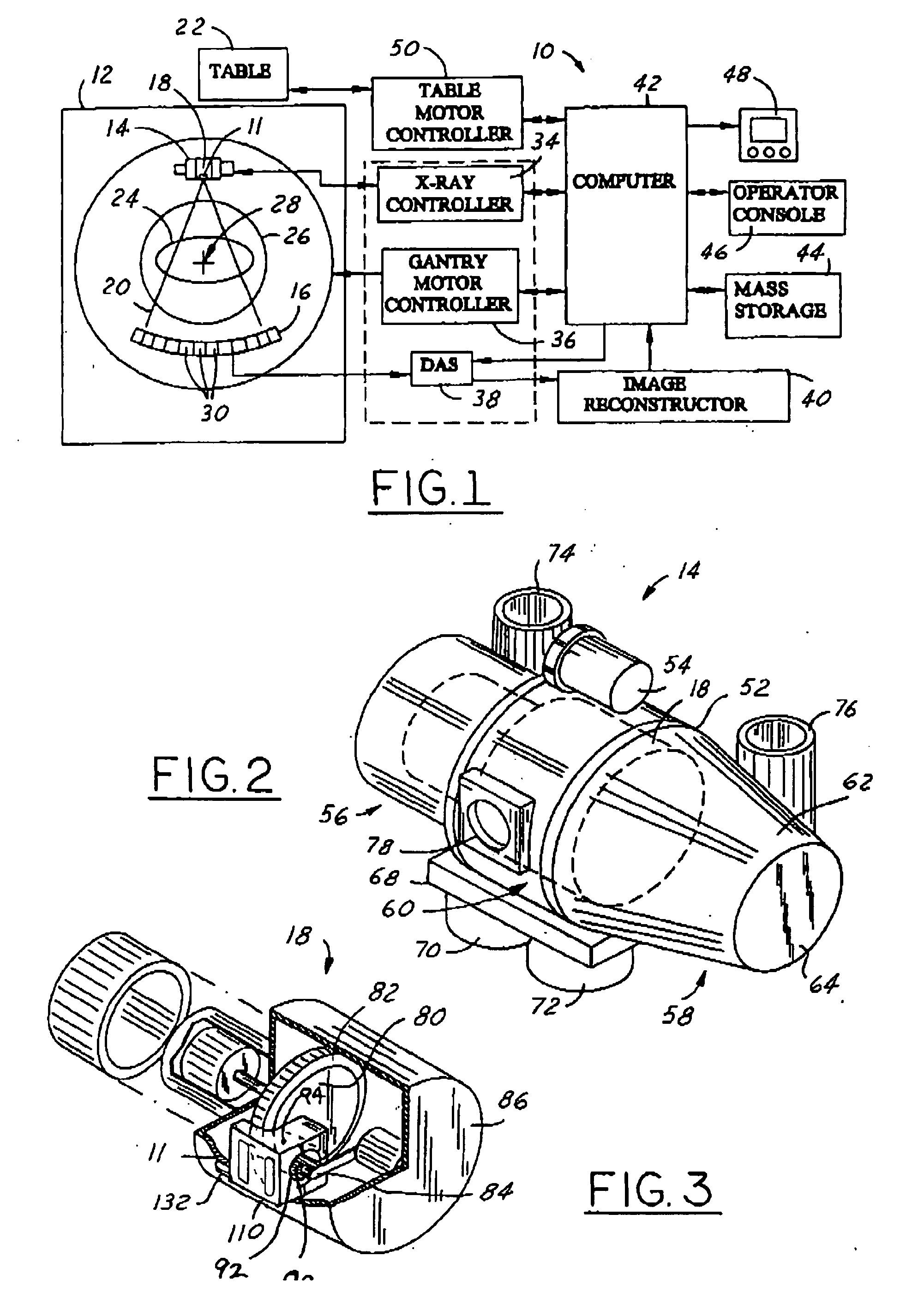
[0027] While the present invention is described with respect to an assembly for cooling an x-ray tube window within a computed tomography (CT) imaging system, the following apparatus and method is capable of being adapted for various purposes and is not limited to the following applications: MRI systems, CT systems, radiotherapy systems, flouroscopy systems, x-ray imaging systems, ultrasound systems, vascular imaging systems, nuclear imaging systems, magnetic resonance spectroscopy systems, and other applications known in the art.

[0028] In the following description, various operating parameters and components are described for one constructed embodiment. These specific parameters and components are included as examples and are not meant to be limiting.

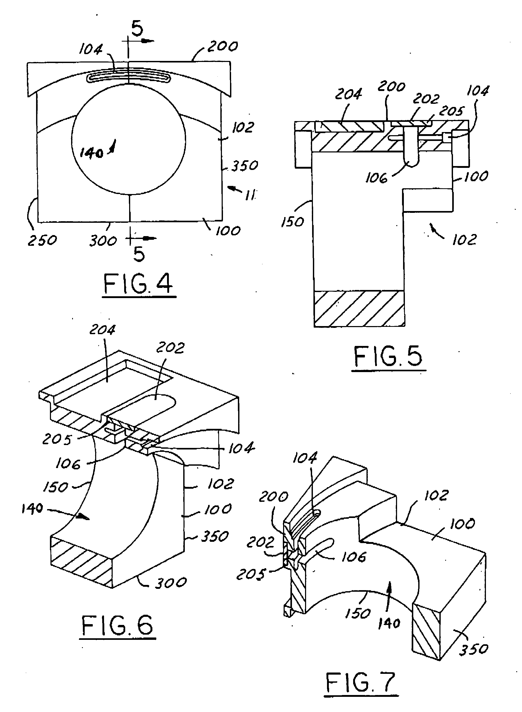
[0029] Also, in the following description the term “impinge” refers to an object colliding directly with another object. For example, as known in the art, an electron beam impinges upon a target of an anode within an x-ray tube. The ...


PUM


Abstract

A slotted window collector assembly for an x-ray tube having an anode and a cathode includes a collector having an anode side and a cathode side, which opposes the anode side. The anode side and the cathode side define an internal bore there between for receiving x-rays from the anode. The slotted collector further includes a window side common to both the anode side and the cathode side and having a window coupled thereto, wherein a window aperture is defined extending from the window to the internal bore. Within the collector assembly, a slot is defined intersecting the window aperture and extending trans-axially thereto and beyond a set length. The slot also extends circumferentially with the window such that plastic strain on the window and heat transferred to the window are reduced.

Description

BACKGROUND OF INVENTION [0001] The present invention relates generally to thermal energy management systems within electron beam generating devices and, more particularly, to an assembly for cooling and relieving stress from an x-ray tube window. [0002] There is a continuous effort to increase x-ray imaging system scanning capabilities. This is especially true in computed tomography (CT) imaging systems. Customers desire the ability to increase the peak power to reduce X-ray doses. The increase in peak power also allows physicians to get improved CT images of vascular applications with high speed CT imaging systems. Although the increase in imaging speed generates improved imaging capability, it causes new constraints and requirements for the functionality of the CT imaging systems. [0003] CT imaging systems include a gantry rotating at various speeds in order to generate a 360° image. The gantry includes an x-ray tube, which composes a large portion of the rotating gantry mass. The...

Claims


Application Information

Patent Timeline
Patent Type & Authority Applications(United States)
IPC IPC(8): G21K1/00H05G1/02H01J35/04H01J35/16H01J35/18
CPCH01J35/16H05G1/025H01J35/18
Inventor WANG, LIQINHEBERT, MICHAEL SCOTTDERAKHSHAN, MARKHOCKERSMITH, RON KENT
Owner GENERAL ELECTRIC CO
Why Eureka
Try Eureka