Determining connectedness and offset of 3D objects relative to an interactive surface

a technology of interactive surfaces and objects, applied in the field of visual detection objects, can solve the problems of failure to discuss the relative separation between, and the function is not provided by touch-sensitive surfaces or screens, and achieve the effect of reducing latency

Inactive Publication Date: 2005-10-13
MICROSOFT TECH LICENSING LLC
View PDF23 Cites 160 Cited by
  • Summary
  • Abstract
  • Description
  • Claims
  • Application Information

AI Technical Summary

Benefits of technology

[0012] The method can further include the step of creating a second pixilated image an interval of time after creating the first pixilated image, followed by the step of creating a third binarized image from the second pixilated image by filtering out pixels of the second binarized image that do not have an intensity exceeding the hover threshold. The second binarized image and the third binarized image thus comprise a sequence of binarized images at the hover threshold. A third connected component is detected in the third binarized image, and at least one of a third bounding area and a third location of the third connected component are determined in the third binarized image. At least one of a current distance from the surface, a change in distance, and a velocity of the 3D object are determined as a function of at least two of the second bounding area, the third bounding area, the second location, and the third location. As a further step, the method can predict whether the 3D object will contact the surface within a predefined period. An indication that the 3D object has already contacted the surface is produced if the prediction indicates that the 3D object will contact the surface within the predefined period, thereby reducing a latency in providing the indication that the 3D object has contacted the surface.

Problems solved by technology

Again, these papers are generally silent regarding the process used for detecting an object based upon the IR light reflected from the object and also fail to discuss determining the relative separation between an object and the display surface.
This function is not provided by touch-sensitive surfaces or screens, for example, most of which are limited to reasoning about one or more discrete points on the surface that correspond to the user's touch.

Method used


Image

  • Determining connectedness and offset of 3D objects relative to an interactive surface
  • Determining connectedness and offset of 3D objects relative to an interactive surface
  • Determining connectedness and offset of 3D objects relative to an interactive surface

Examples


Embodiment Construction

Exemplary Computing System for Implementing Present Invention

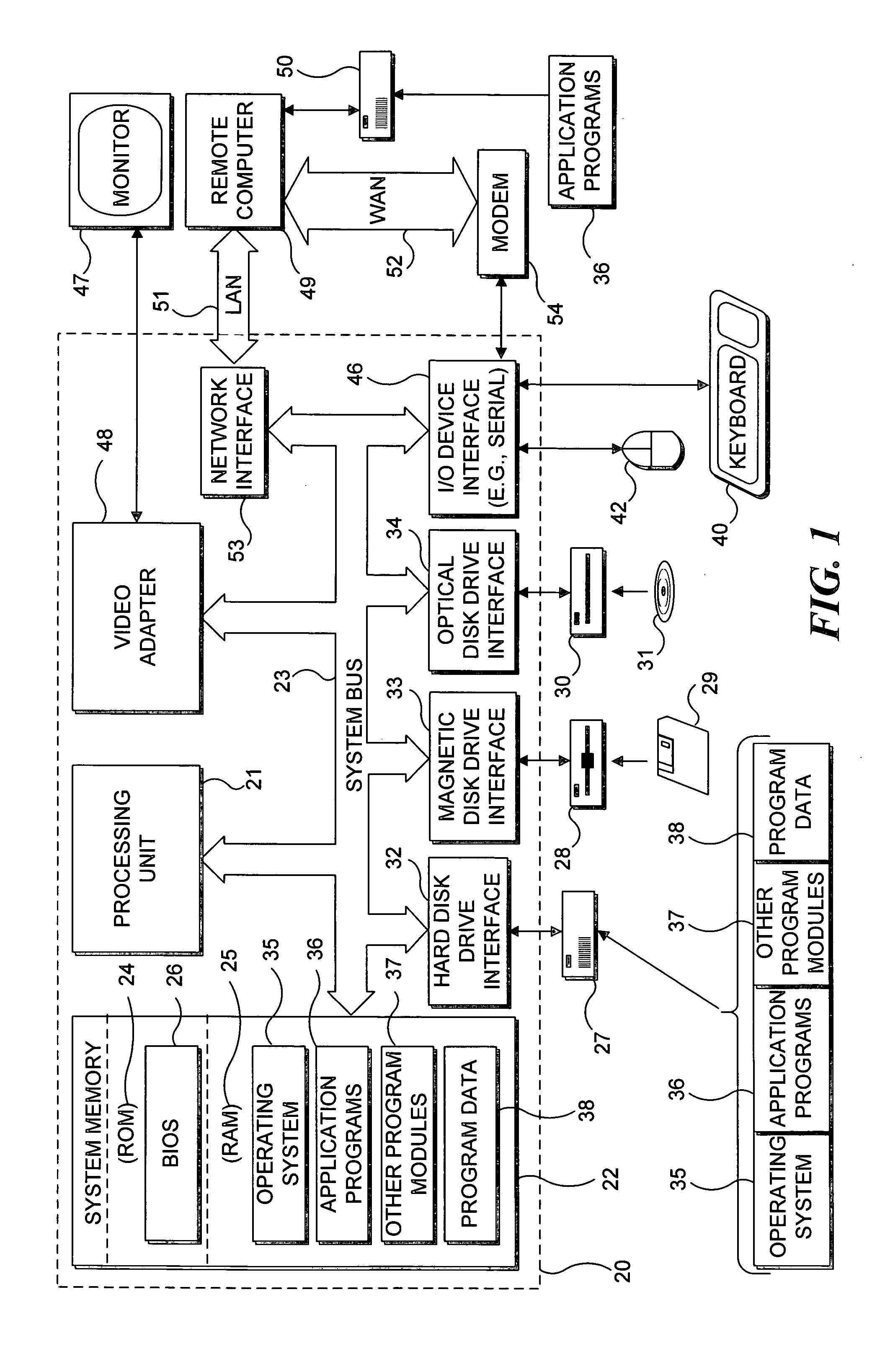
[0027] With reference to FIG. 1, an exemplary system suitable for implementing various portions of the present invention is shown. The system includes a general purpose computing device in the form of a conventional PC 20, provided with a processing unit 21, a system memory 22, and a system bus 23. The system bus couples various system components including the system memory to processing unit 21 and may be any of several types of bus structures, including a memory bus or memory controller, a peripheral bus, and a local bus using any of a variety of bus architectures. The system memory includes read only memory (ROM) 24 and random access memory (RAM) 25. A basic input / output system 26 (BIOS), containing the basic routines that help to transfer information between elements within the PC 20, such as during start up, is stored in ROM 24. PC 20 further includes a hard disk drive 27 for reading from and writing to a hard disk ...


PUM


Abstract

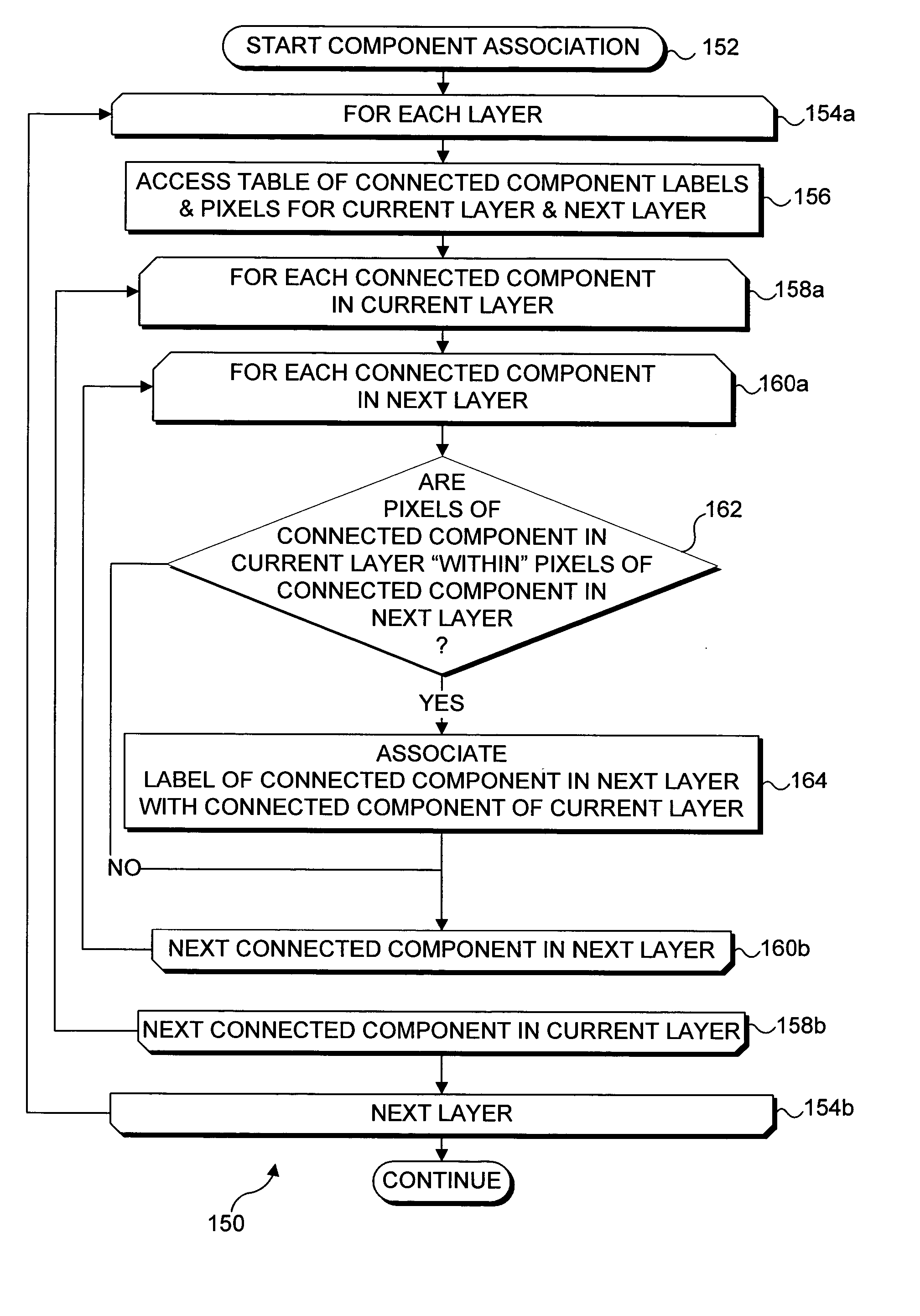
A position of a three-dimensional (3D) object relative to a display surface of an interactive display system is detected based upon the intensity of infrared (IR) light reflected from the object and received by an IR video camera disposed under the display surface. As the object approaches the display surface, a “hover” connected component is defined by pixels in the image produced by the IR video camera that have an intensity greater than a predefined hover threshold and are immediately adjacent to another pixel also having an intensity greater than the hover threshold. When the object contacts the display surface, a “touch” connected component is defined by pixels in the image having an intensity greater than a touch threshold, which is greater than the hover threshold. Connected components determined for an object at different heights above the surface are associated with a common label if their bounding areas overlap.

Description

FIELD OF THE INVENTION [0001] The present invention generally pertains to visually detecting objects that are adjacent to a display surface of an interactive display system, and more specifically, pertains to detecting connected pixels in an image of an object and determining its relative separation from the display surface, where the image is formed in response to light reflected from the object through the display surface. BACKGROUND OF THE INVENTION [0002] Several interactive displays are known in the prior art. For example, a user interface platform was developed in the MIT Media Lab, as reported by Brygg Ullmer and Hiroshi Ishii in “The metaDESK: Models and Prototypes for Tangible User Interfaces,”Proceedings of UIST October 1997:14-17. This article describes how the metaDESK includes a near-horizontal graphical surface that is used to display two-dimensional (2D) geographical information. A computer vision system inside the desk unit (i.e., below the graphical surface) include...

Claims


Application Information

Patent Timeline
Patent Type & Authority Applications(United States)
IPC IPC(8): G06F3/042G06K9/00G06K9/34
CPCG06F3/0425G06F2203/04101G06K9/00375G06V40/107
Inventor WILSON, ANDREW D.
Owner MICROSOFT TECH LICENSING LLC
Why Eureka
Try Eureka