Nozzle having a nozzle body with heated and unheated nozzle body segments

Active Publication Date: 2005-10-13
MOLD MASTERS 2007
View PDF31 Cites 20 Cited by
  • Summary
  • Abstract
  • Description
  • Claims
  • Application Information

AI Technical Summary

Benefits of technology

[0013] The intermediate nozzle body segment is interlocked or connected to the other two nozzle body segments by a threaded engagement, brazing, welding, fusing, a press fit engagement or an interference fit engagement. In one embodiment, the intermediate nozzle body segment can be removably attached to the other two nozzle body segments, so that intermediate nozzle body segments of varying lengths can be used depending on the particular part to be molded. The intermediate nozzle body segment is made of a thermally conductive material. Depending on each particular application, the material of the intermediate nozzle body segment can have either a higher, an equal or a slightly lower thermal conductivity than the material of the other t

Problems solved by technology

The intermediate nozzle body segment, however, is

Method used


Image

  • Nozzle having a nozzle body with heated and unheated nozzle body segments
  • Nozzle having a nozzle body with heated and unheated nozzle body segments
  • Nozzle having a nozzle body with heated and unheated nozzle body segments

Examples


Embodiment Construction

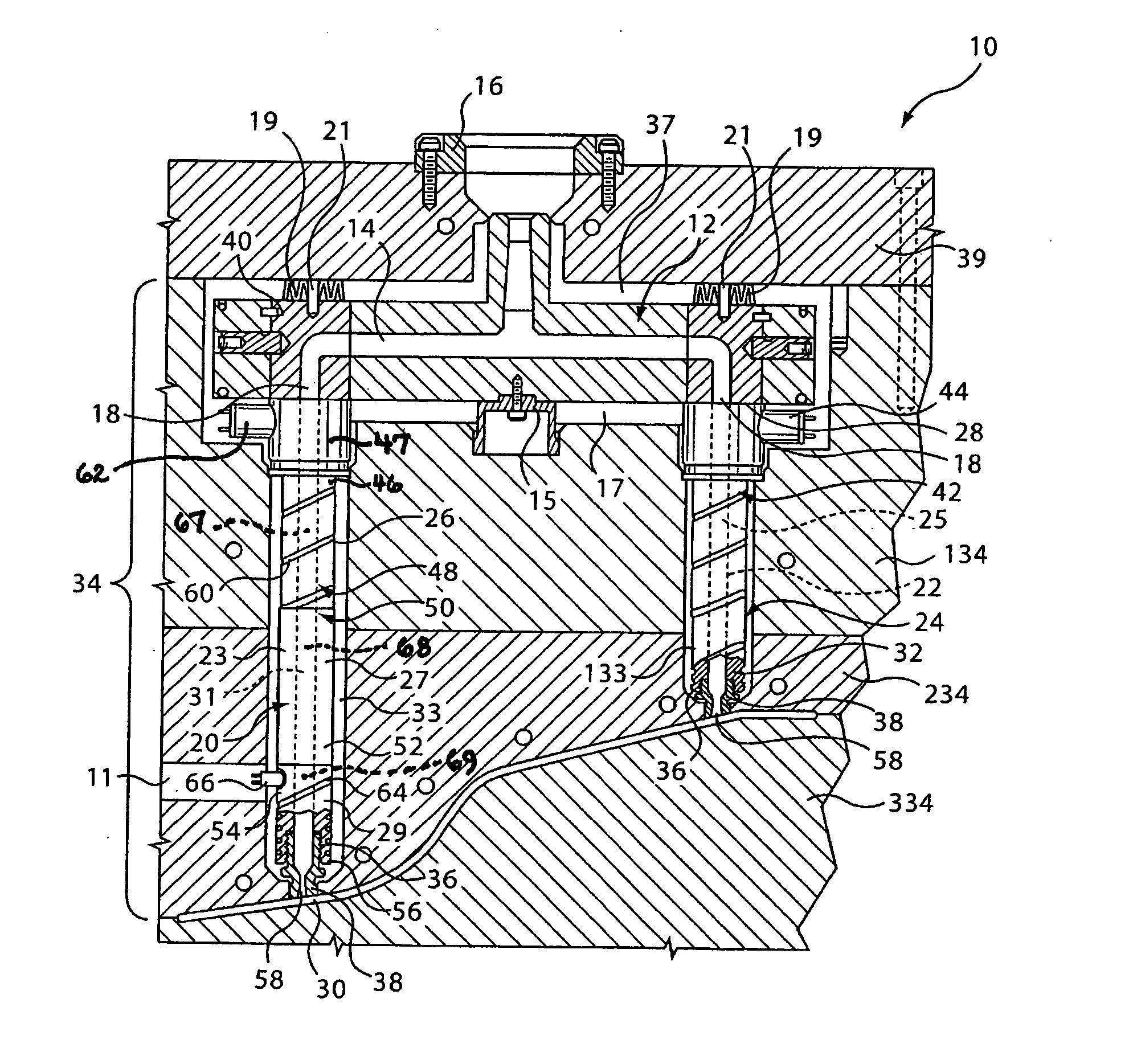
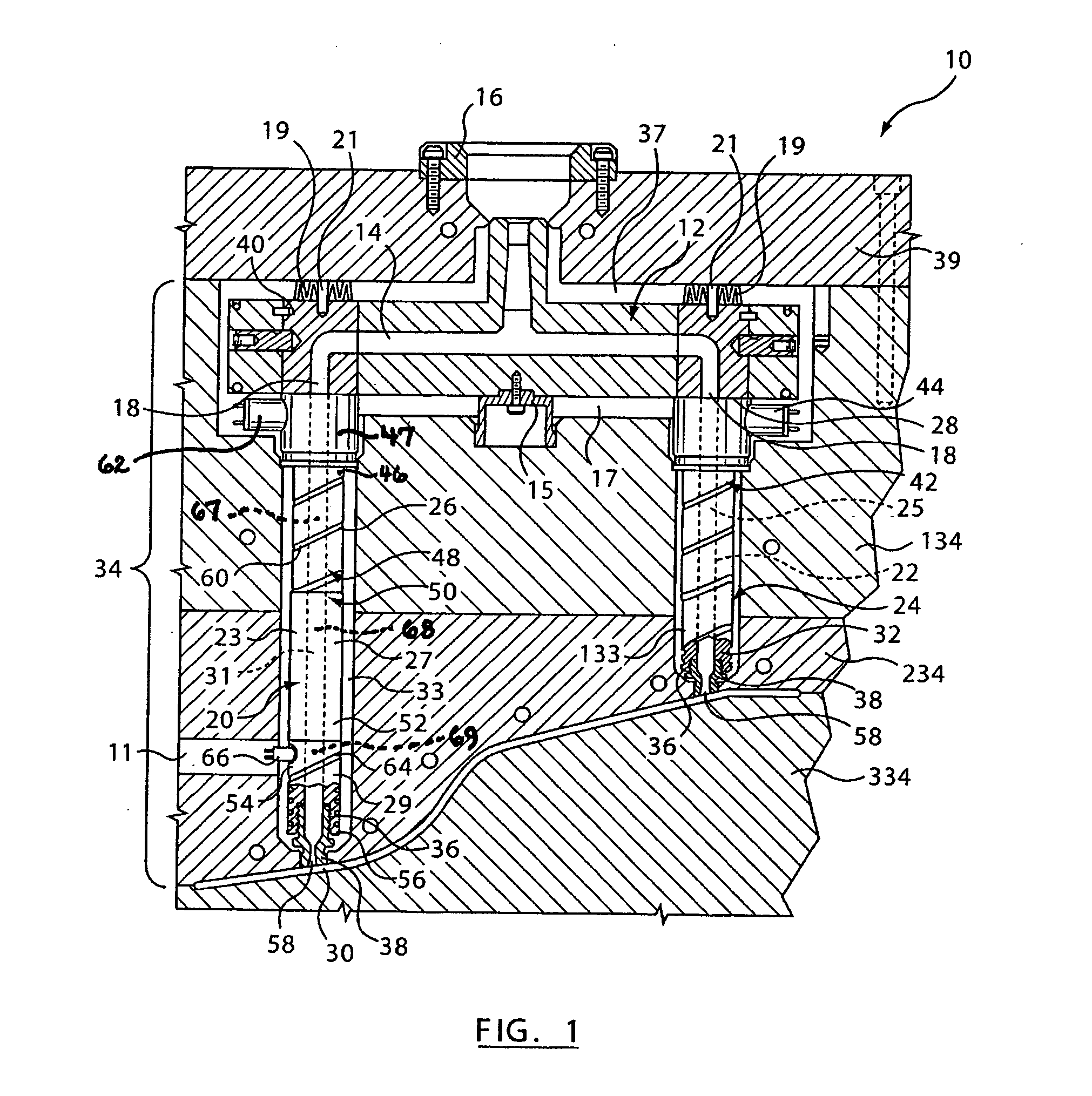
[0034] Referring now to FIG. 1, an injection molding apparatus 10 is generally shown. The injection molding apparatus 10 includes a manifold 12 having a manifold channel 14 extending therethrough. A manifold bushing 16 is located at an inlet of the manifold channel 14 to receive a melt stream of moldable material from a machine nozzle (not shown) and to deliver the melt stream to manifold outlets 18. A heating element (not shown) heats manifold 12 to maintain the melt stream passing through manifold channel 14 at a desired temperature. The heating element of the manifold may be embedded into or otherwise surround a surface of the manifold 12. The manifold 12 is secured in position by a central locating ring 15 which bridges an insulative air space 17 between the heated manifold 12 and a cooled mold plate 134. Another insulative air space 37 of a predetermined width is located between the heated manifold 12 and a cooled clamp plate 39. Pressure discs 19 are mounted by screws 21 to cr...


PUM

PropertyMeasurementUnit
Lengthaaaaaaaaaa
Diameteraaaaaaaaaa
Electrical conductoraaaaaaaaaa

Abstract

A nozzle for an injection molding apparatus includes a nozzle body having a first nozzle body segment, a second nozzle body segment and a third nozzle body segment. The second nozzle body segment is removably connected to at least one of the first nozzle body segment and the third nozzle body segment. The first nozzle body segment and the third nozzle body segment are heated either by first and second nozzle heaters, respectively, or by a heater sleeve having a cut-out along the length of the second nozzle body segment. The second nozzle body segment is substantially devoid of a nozzle heater such that the second nozzle body segment is heated passively through contact with the first nozzle body segment and the third nozzle body segment.

Description

CROSS-REFERENCE TO RELATED APPLICATIONS [0001] This application claims the benefit of U.S. provisional patent applications 60 / 559,977, filed Apr. 7, 2004, and 60 / 618,996, filed Oct. 18, 2004, which are hereby incorporated by reference in their entirety herein.BACKGROUND OF THE INVENTION [0002] 1. Field of the Invention [0003] The present invention relates generally to an injection molding apparatus and, in particular to a nozzle having a nozzle body with multiple nozzle body segments. More particularly, the present invention relates to an injection nozzle in which at least one of the nozzle body segments of the nozzle body is heaterless. [0004] 2. Background of the Invention [0005] As is well known in the art, hot runner injection molding systems include a manifold for conveying pressurized melt from an inlet to one or more manifold outlets. A plurality of nozzles are typically coupled to the manifold outlets for conveying the melt to a plurality of mold cavities. [0006] In some app...

Claims


Application Information

Patent Timeline
IPC IPC(8): B29C45/28B29C45/27B29C45/38
CPCB29C45/27B29C45/2701B29C45/2737B29C45/2738B29C45/2806B29C2045/2777B29C2045/2741B29C2045/2754B29C2045/2766B29C2045/2774B29C2045/2717
Inventor FISCHER, JONATHONFAIRY, FABRICECOLONICO, GINOTABASSI, PAYMAN
Owner MOLD MASTERS 2007
Why Eureka
Try Eureka