Sealant Plug Delivery Methods

Inactive Publication Date: 2005-10-13
MEDICAL DEVICE TECH
View PDF9 Cites 88 Cited by
  • Summary
  • Abstract
  • Description
  • Claims
  • Application Information

AI Technical Summary

Benefits of technology

[0037] An important object of this invention is to provide an apparatus for delivering and deploying a bi

Problems solved by technology

Air leaks commonly occur at pulmonary tissue sites that have been dissected during surgical resection and manipulation or surgical resection or manipulation.
Air leaks also occur after fine needle aspiration biopsy of the lung.
An ope

Method used


Image

  • Sealant Plug Delivery Methods
  • Sealant Plug Delivery Methods
  • Sealant Plug Delivery Methods

Examples


first embodiment

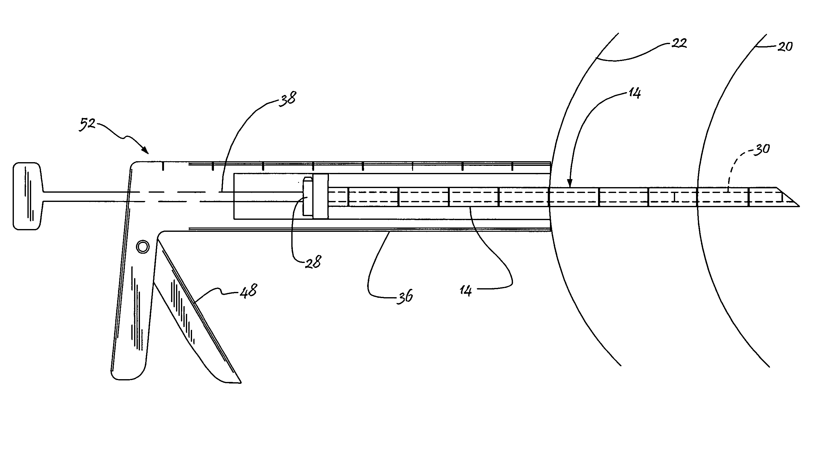
[0087] Graduation markers 52 are imprinted, notched, or otherwise affixed to supporting leg 36 as depicted. Holder 28 is mounted upon plunger 38. The chart referred to in the disclosure of the first embodiment is consulted and plunger 38 and supporting leg 36 are positioned relative to one another in accordance with the CT scan measurement-based chart of FIG. 6A. In FIG. 11, holder 28 is positioned at the 4th graduation marker.

[0088] For example, suppose a particular CT scan measurement is made and the distance from the surface of the patient's skin to the internal organ (distance “a”) is determined to be 3.0 cm. That measurement is looked up in the chart of FIG. 6A and the chart says to set marker 28 on the “4th notch.” Trigger 48 is pulled to release plunger 38 and said plunger is withdrawn or retracted until holder 28 is aligned with the fourth graduation marker. That particular setting is depicted in FIG. 11. Trigger 48 is then released to lock plunger 38 into the selected posit...

third embodiment

[0094] In a third embodiment, plunger 38a (FIG. 13) is provided in the form of a tube having slot 54 formed in its distal end, thereby forming bifurcated ends that may be spread apart from one another. The inside diameter of tube 38a is smaller than the outside diameter of sealant plug 30. Significantly, plunger 38a is formed of a flexible and resilient material with memory, such as nitinol, so that slot 54 may be opened as at 56 in FIG. 13B.

[0095] When the distal end of plunger 38a is opened as at 56 by spreading said ends apart, the trailing or proximal end of bioabsorbable sealant plug 30 is then positioned between said open ends as indicated by assembly arrow 58 in FIG. 13B.

[0096] As depicted in FIG. 14, sleeve 60 is then advanced in a trailing-to-leading direction, thereby closing the distal end of plunger 38 until it returns to its FIG. 13A position where it clamps down on plug 30. Sleeve 60 is omitted from FIGS. 13A and 13B to simplify said Figures.

[0097] When sleeve 60 is ...

fourth embodiment

[0098] A fourth embodiment is disclosed in FIGS. 16 and 17. Holder 62 in FIG. 16 includes threaded turning nut 64 having a general “E” shape. Holder 64 further includes leading end 66 that advances in a trailing-to-leading direction, as indicated by single-headed directional arrow 68, when turning nut 64 is screw-threadedly advanced. The external surface of housing 70 is complementally threaded to engage said turning nut 64.

[0099] Longitudinally-extending throughbore 72 is formed in housing 70 and extends therethrough from the trailing to the leading end thereof. The trailing end of bore 72 accommodates leading end 66 of turning nut 64. Flat washer 74 is positioned in leading relation to leading end 66 and said flat washer is therefore constrained to displace in a trailing-to-leading direction, indicated by said directional arrow 68, when turning nut 64 is advanced.

[0100] Silicon gasket 76 of frusto-conical configuration is positioned in leading relation to flat washer 74 and is al...


PUM


Abstract

A bioabsorbable sealant plug that expands in response to contact with moisture in a mammalian body is optimally positioned in a biopsy tract to seal the biopsy tract when a biopsy procedure is completed. In a first method, the leading end of the sealant plug is advanced through the lumen of a coaxial needle by a plunger until a leading end of a supporting leg abuts the patient's skin surface. A second method is performed with a pistol-shaped tool having a trigger that enables adjustment of the plunger. A third embodiment includes a plunger having a bifurcated end that grasps the plug. A fourth embodiment has a turning nut that causes compression of a gasket that clamps down on the plug. A supporting rod and coaxial needle are in parallel relation to one another in a fifth embodiment.

Description

CROSS REFERENCE TO RELATED APPLCIATION [0001] This application is a continuation of U.S. patent application Ser. No. 10 / 248,261 filed on Dec. 31, 2002, entitled “Sealant Plug Delivery Methods.”BACKGROUND OF THE INVENTION [0002] 1. Field of the Invention [0003] This invention relates, generally, to methods for sealing biopsy tracts. More particularly, it relates to apparatus and methods that enable precise positioning of a bioabsorbable sealant plug in a predetermined optimal location. [0004] 2. Description of the Prior Art [0005] Air leaks commonly occur at pulmonary tissue sites that have been dissected during surgical resection and manipulation or surgical resection or manipulation. Air leaks also occur after fine needle aspiration biopsy of the lung. Pneumothorax (air leakage) occurs in about thirty percent (30%) of lung biopsies. An opening in a lung is undesirable because air leaks therefrom and causes the lung to collapse. Openings in other organs, such as the heart, liver, ki...

Claims


Application Information

Patent Timeline
IPC IPC(8): A61B10/00A61B10/02A61B17/00A61B19/00
CPCA61B10/0233A61B2019/462A61B2017/00004A61B17/00491A61B2090/062
Inventor FISHER, JOHN SAHARI, FREDERICK
Owner MEDICAL DEVICE TECH
Why Eureka
Try Eureka