Chemical filtration unit incorporating air transportation device

a technology of air transportation device and filtration unit, which is applied in the direction of auxillary pretreatment, heating type, separation process, etc., can solve the problems of high final product weight, high pressure drop, and turbulent path of air flowing through the assembly, and achieve the effect of significantly reducing assembly weight, cost, and pressure drop through the assembly

Inactive Publication Date: 2005-10-20
DONALDSON CO INC
View PDF16 Cites 29 Cited by
  • Summary
  • Abstract
  • Description
  • Claims
  • Application Information

AI Technical Summary

Benefits of technology

[0010] By having a low-pressure drop chemical filter and particulate filter, according to this disclosure, the overall assembly weight, cost, and pressure drop through the as

Problems solved by technology

These tightly packed beds result in a torturous path for air flowing through the bed
Ion exchange resin beads have improved capacity and faster reaction mechanism over modified activated carbons for acid or bas

Method used


Image

  • Chemical filtration unit incorporating air transportation device
  • Chemical filtration unit incorporating air transportation device
  • Chemical filtration unit incorporating air transportation device

Examples


second embodiment

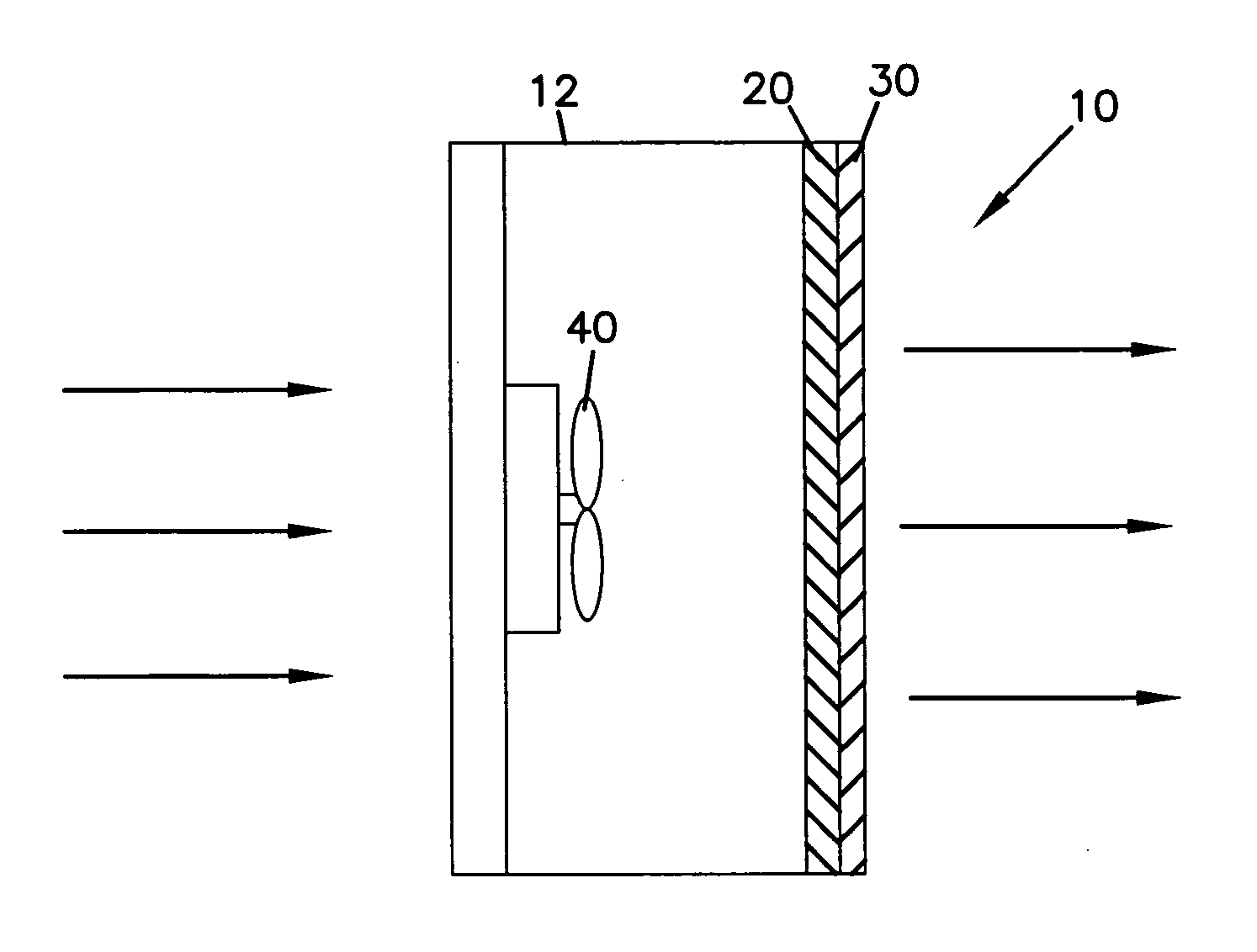
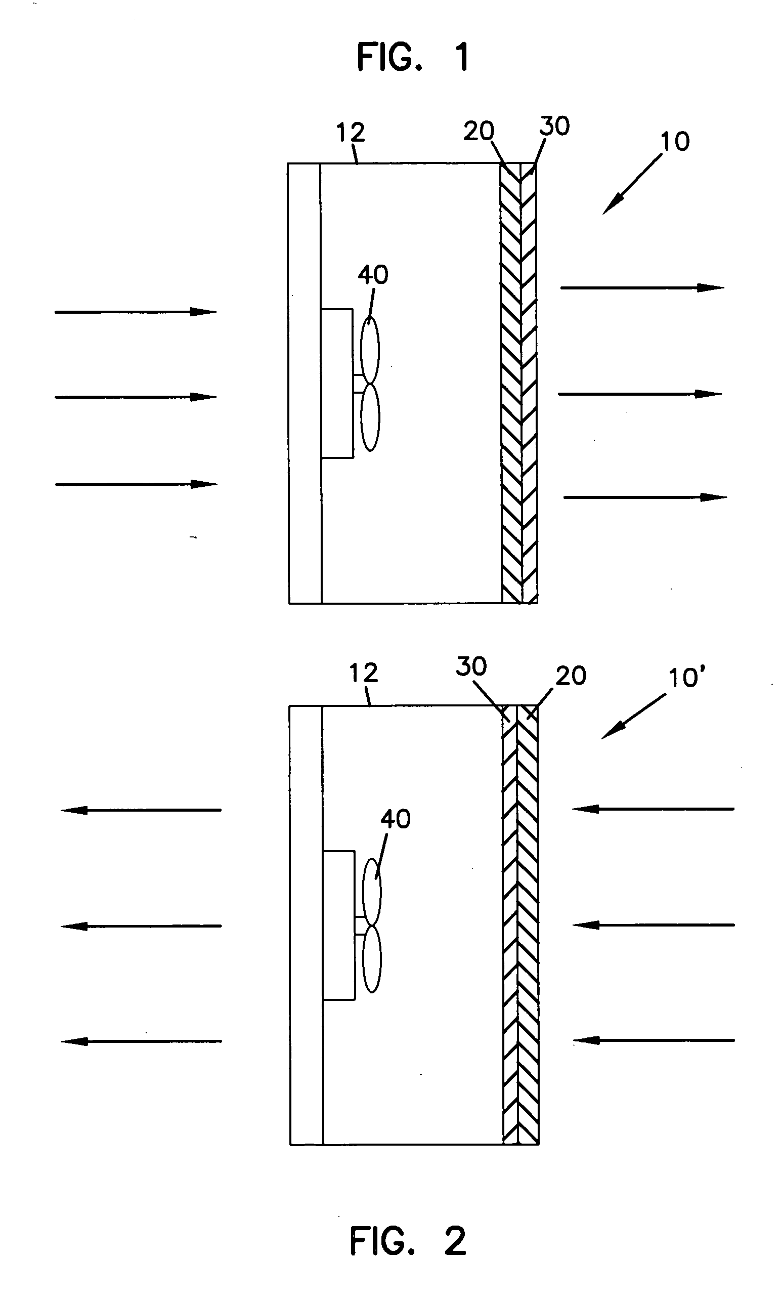
[0019] a filtration assembly 10′ is illustrated in FIG. 2. Similar to the embodiment of FIG. 1, filtration assembly 10′ has housing 12 in which is positioned low-pressure drop chemical filter 20, low-pressure drop particulate filter 30, and air moving equipment 40, such as fan.

[0020] In FIG. 2, fan 40 pulls air or other gas to be filtered into assembly 10 through chemical filter 20 and particulate filter 30. In the configuration illustrated, chemical filter 20 is upstream of particulate filter 30; in alternate embodiments, particulate filter 30 may be upstream of chemical filter 20.

[0021] It is preferred that the pressure drop through the combination of chemical filter 20 and particulate filter 30 is no greater than 2 inch water at an airflow filter face velocity of 0.5 m / s. Preferably, the pressure drop is no greater than 1 inch water at an airflow filter face velocity of 0.5 m / s, and even more preferably no greater than 0.5 inch water at an airflow filter face velocity of 0.5 m / s...

first embodiment

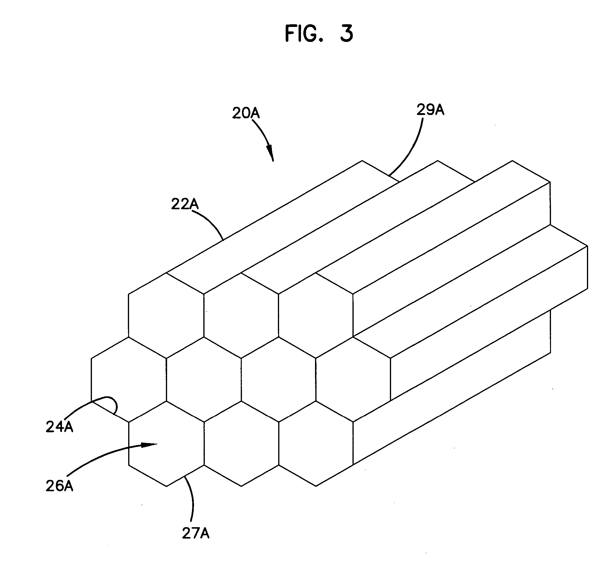
[0024] Referring now to the figures, specifically to FIG. 3, a low-pressure drop chemical filter 20 is shown at 20A. Such a chemical filter is described in U.S. Pat. No. 6,645,271, which is incorporated herein by reference in its entirety. Chemical filter 20A is defined by a structured body 22A having a first face 27A and a second face 29A. Body 22A includes a plurality of cells 24A therein. Preferably, cells 24A are present in a non-random, orderly array. Cells 24A define passages 26A through body 22A that extend from first face 27A to second face 29A. Filter 20A has “straight-through flow” or “in-line flow”, meaning that gas to be filtered enters in one direction through first face 27A and exits in generally the same direction from second face 29A. Present on the interior walls of cells 24A is an adsorptive coating that has an adsorptive media retained on cells 24A by a polymeric resin or adhesive. The coating is present within cells 24A yet allows air or other fluid to move throu...


PUM

PropertyMeasurementUnit
Lengthaaaaaaaaaa
Lengthaaaaaaaaaa
Speedaaaaaaaaaa

Abstract

The present invention overcomes the limits of activated carbons, ion exchange resin beads and fibers, and liquid form ion exchangers for acid, base, or VOCs gases removal by providing a filtration assembly for the filtration of chemical contaminants and particulates from an air or gas stream, the assembly having a low pressure-drop structure. The filtration assembly includes a low-pressure drop chemical filter, a low-pressure drop particulate filter, and an air transportation device, such as a fan or blower, all combined in a housing.

Description

[0001] Priority under 35 U.S.C. §119(e) is claimed to U.S. provisional application No. 60 / 562,864, filed Apr. 16, 2004. The complete disclosure of provisional application No. 60 / 562,864 is incorporated herein by reference.FIELD OF THE DISCLOSURE [0002] The present disclosure is related to air filtering systems for removing contaminants, particularly chemical contaminants such as acids, bases, or VOC gases from a gas stream, such as an air stream. The air filtering systems are particularly adapted for removing contaminants from air streams having a low level (<100 ppm) of contaminant. BACKGROUND [0003] Filters and filtration systems that include activated carbons are widely used to remove VOCs from an air stream. The carbons can be modified with acids or bases to remove base or acid gases. The chemical contaminants, such as the VOCs, base contaminants and acid contaminants, are either adsorbed or absorbed by the carbon material. These adsorption materials are typically used in pac...

Claims


Application Information

Patent Timeline
IPC IPC(8): B01D46/12B01D53/34F24F3/16
CPCB01D46/0023B01D2273/30B01D53/34B01D46/10Y02A50/20B01D46/62
Inventor DALLAS, ANDREW JAMESDING, LEFEIJORIMAN, JON DENNISPARSONS, JONATHAN GEORGE
Owner DONALDSON CO INC
Why Eureka
Try Eureka