Eureka AIR delivers breakthrough ideas for toughest innovation challenges, trusted by R&D personnel around the world.

Capacitance activated switch device

Active Publication Date: 2005-10-20
WABTEC HLDG CORP
View PDF11 Cites 19 Cited by
  • Summary
  • Abstract
  • Description
  • Claims
  • Application Information

AI Technical Summary

Benefits of technology

[0019] In one aspect, the present invention overcomes the disadvantages of the presently used switch devices for opening doors by employing an electric field imaging device electrically coupled via an electrical antenna conductor to a conductive electrode member that is attached to the door or any other suitable surfaces with the use of electrical isolating spacers. Such electric field imaging device generates a sine wave of a predetermined frequency, which is transmitted to the electrode member thus producing a surrounding electrical field. A resistor of a predetermined value is electrically coupled intermediate the wave generator and the conductive electrode member. Any body part, such as hand, arm, shoulder, or torso, which enters such electrical field, will create a capacitive load due to the body being grounded to a floor surface. Reduction in distance between the body part and the conductive electrode will increase the capacitance and will decrease the voltage intermediate the resistor and conductive electrode which is an inverse function of the capacitance. Such change in voltage will be detected by a combination of the electric field imaging device and a microcontroller coupled thereto by comparing voltages at each end of the resistor and the change exceeding a predetermined threshold will be associated with an output signal. Such output signal, when received by a door controller, will be interpreted thereby as a request to open the door enabling a door drive connected to the door to move it in an opening direction. Because the change in voltage will be detected prior to physical contact between the passenger and the conductive electrode member, the opening of the door will not require the passenger to apply pressure. The electric field imaging device and the microcontroller may be mounted to a printed circuit board that can be disposed within a housing of the touch bar, in the space occupied by the electromechanical switch or may be adapted with its own housing and disposed adjacent the conductive electrode member in a touch tape switch configuration. In alternative configurations, the door itself manufactured form conductive material may be used as a switch device or the electrical antenna conductor may be imbedded in a glass portion of the door thus enabling the passenger to open the door by approaching such glass portion.
[0025] Still another object of the present invention is to provide a capacitance activated switch device that reduces manufacturing costs.

Problems solved by technology

Additionally, partially operating side door systems decreases component wear and increases durability and reliability of such side door systems.
One disadvantage of such devices is that they contain moving components, which decrease performance reliability over time and are associated with increased manufacturing costs.
Another disadvantage of such devices is that they require a pressure to be applied thereto in order to achieve activation, thus making their use more difficult for a disabled person or child.
The main disadvantage of the first three methods is that obstruction detection is enabled only upon physical contact with the passenger or object which is not desirable when such passenger is a small child or an adult with limited physical capabilities as the contact with the moving door may result in some form of injury.
Utilization of remote sensors in the fourth method eliminates physical contact but is generally costly to implement and is subject to precise tuning in order to properly define coverage area and minimize external noise.

Method used


Image

  • Capacitance activated switch device
  • Capacitance activated switch device
  • Capacitance activated switch device

Examples


Embodiment Construction

, particularly, when the detailed description is taken in conjunction with the attached drawing figures and with the appended claims.

BRIEF DESCRIPTION OF THE DRAWINGS

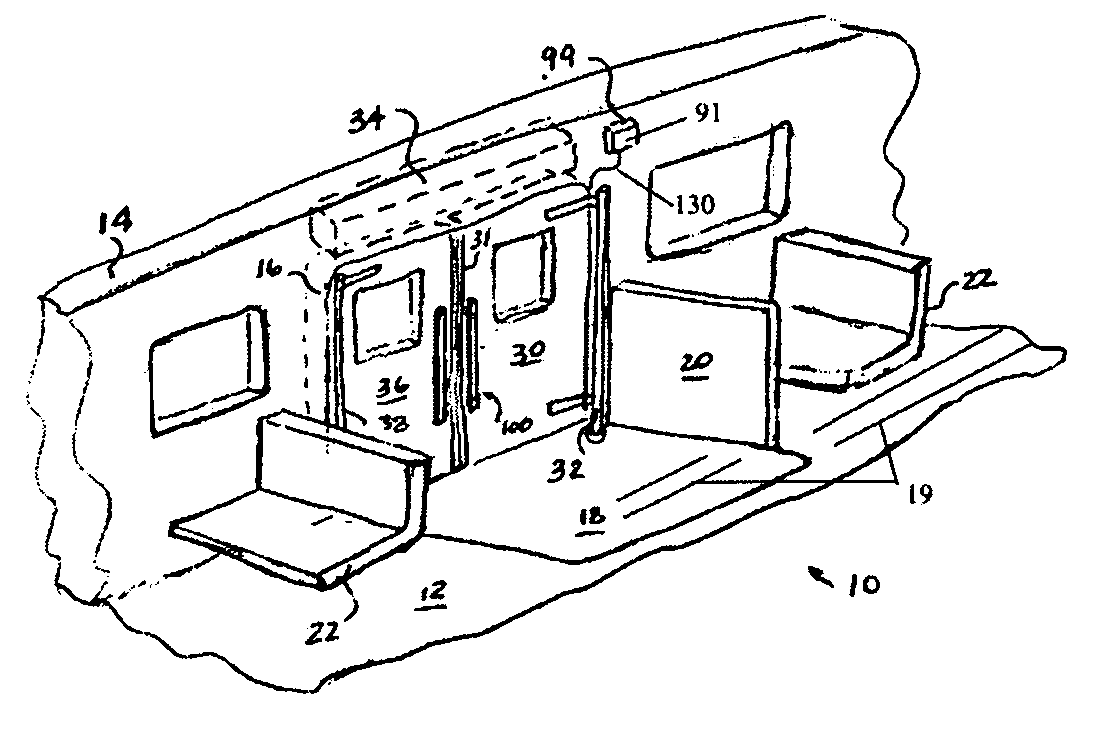
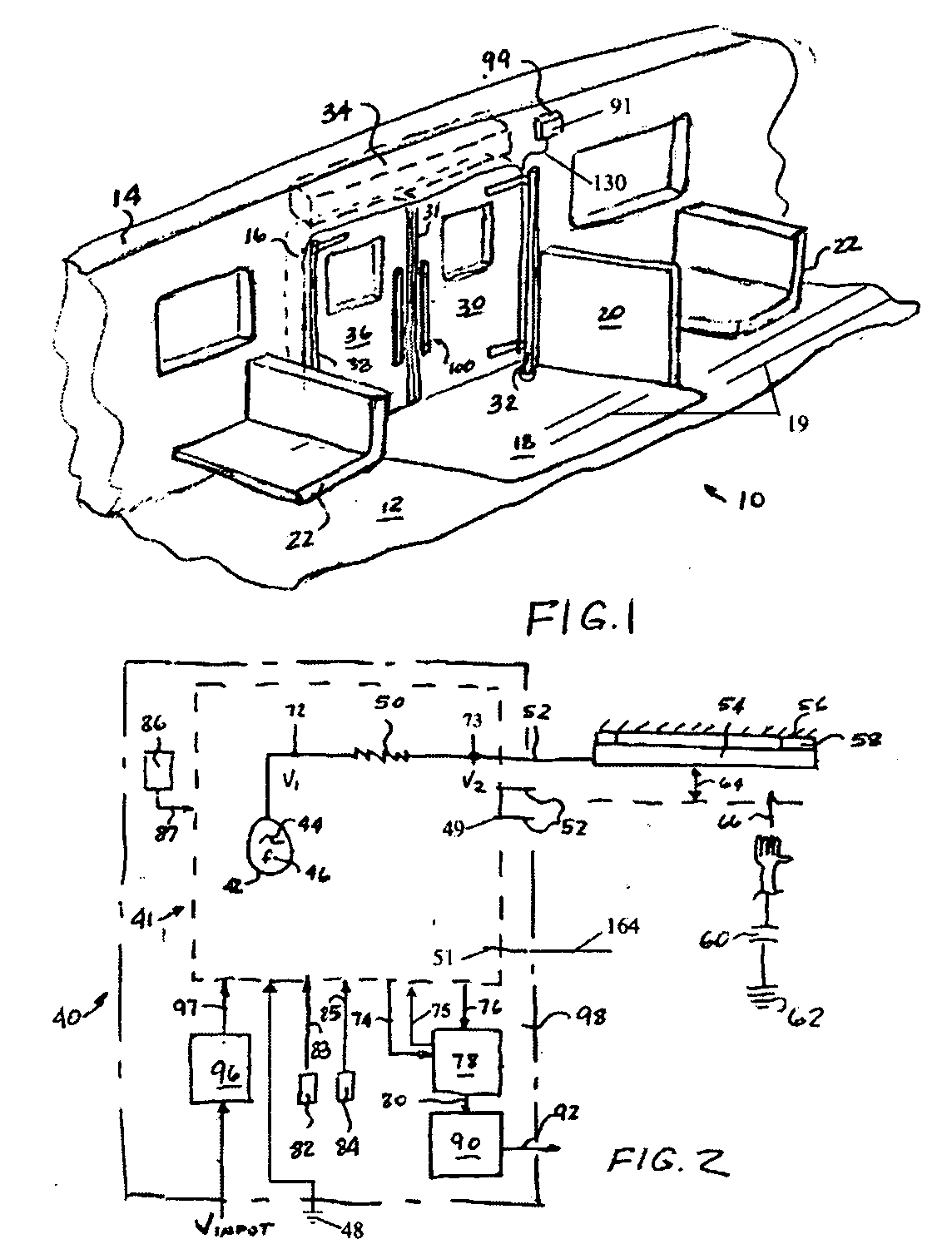
[0029]FIG. 1 is a partial perspective view of a transit vehicle;

[0030]FIG. 2 is a schematic diagram of a capacitance activated switch device of the present invention;

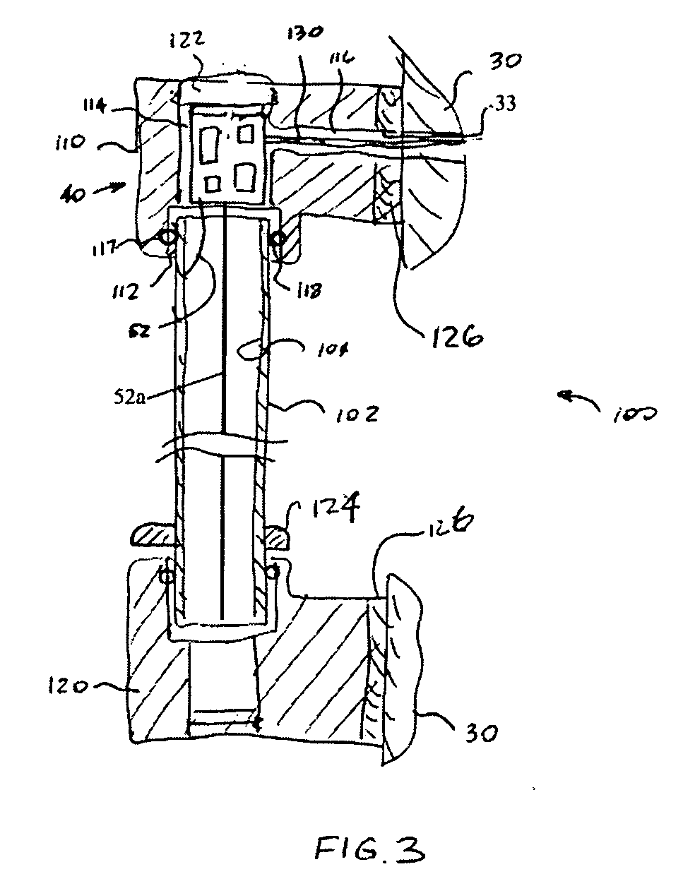
[0031]FIG. 3 is a cross-sectional elevation view of a touch bar for the transit vehicle in combination with the capacitance activated switch device of the present invention;

[0032]FIG. 4 is a front elevation view of the touch switch of the present invention;

[0033]FIGS. 5a-5b are cross-sectional views of the touch switch along lines 5-5 in FIG. 4 particularly showing an alternative disposition of the capacitance activated switch device of the present invention;

[0034]FIG. 6 is a front elevation view of the capacitance activated switch device of the present invention in combination with the door handle;

[0035]FIG. 7 is a partial top view of the doors of t...


PUM


Abstract

A capacitance based switch device employs an electric field imaging device electrically coupled via an electrical conductor to a conductive electrode member that is attached to the door or any other suitable surface. Such electric field imaging device generates a sine wave which is transmitted to the conductive electrode member and produces a surrounding electrical field. Any human body part which enters such electrical field will create a capacitance load due to the body being grounded to a surface. Reduction in distance between the body part and the conductive electrode will increase the capacitance and will decrease the voltage intermediate the resistor and conductive electrode which is an inverse function of the capacitance. Such change in voltage will be detected by a microcontroller by comparing voltages at each end of the resistor and the change exceeding a predetermined threshold will be associated with an output control signal.

Description

CROSS-REFERENCE TO RELATED APPLICATIONS [0001] This application is related to and claims priority from U.S. Provisional Patent Application Ser. No. 60 / 563,167 filed on Apr. 16, 2004.FIELD OF THE INVENTION [0002] The present invention relates, in general, to a switch device and, more particularly, the instant invention relates to a switch device operable by a capacitive load and, still more particularly, the instant invention relates to a capacitance activated switch device for use in a transit vehicle. BACKGROUND OF THE INVENTION [0003] The following background information is provided to assist the reader to understand the environment in which the invention will typically be used. The terms used herein are not intended to be limited to any particular narrow interpretation unless specifically stated otherwise in this document. [0004] It is well known that a vast majority of urban transit vehicles utilize a plurality of side mounted powered door systems for passenger ingress and egres...

Claims


Application Information

Patent Timeline
IPC IPC(8): H03K17/955H03K17/96
CPCH03K17/955H03K2217/960755H03K17/962
Inventor URMAN, ROBERTCITTA, JAMES W.
Owner WABTEC HLDG CORP
Why Eureka
Eureka Blog
Learn More