Synchronous induction motor and electric hermetic compressor using the same

Active Publication Date: 2005-10-20
PANASONIC APPLIANCES REFRIGERATION DEVICES SINGAPORE
View PDF14 Cites 24 Cited by
  • Summary
  • Abstract
  • Description
  • Claims
  • Application Information

AI Technical Summary

Problems solved by technology

Additionally, enlarged diameter of thermistor 13 increases the heat capacity of thermistor 13, causing difficulty in fast cooling.
Namely, a longer ti

Method used


Image

  • Synchronous induction motor and electric hermetic compressor using the same
  • Synchronous induction motor and electric hermetic compressor using the same
  • Synchronous induction motor and electric hermetic compressor using the same

Examples


exemplary embodiment 2

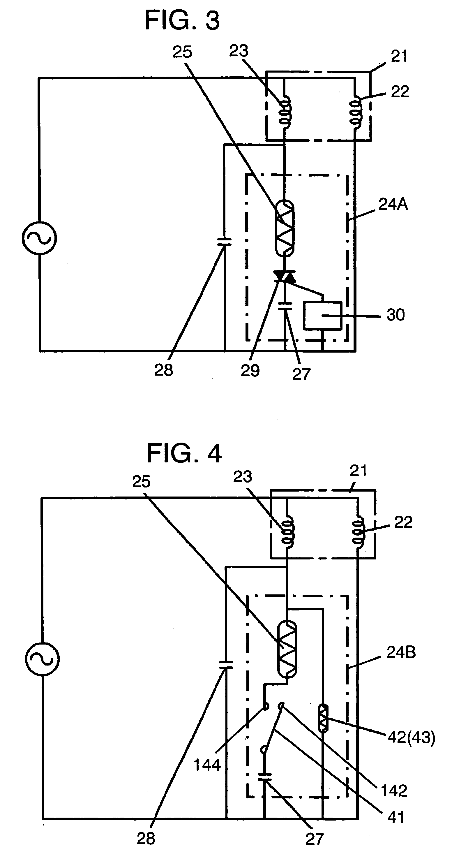
[0041]FIG. 4 shows a circuit diagram of a synchronous induction motor used in a second exemplary embodiment of the present invention. As shown in FIG. 4, starter 24B includes thermistor 25, starting capacitor 27, bimetal switch 41, and auxiliary positive temperature coefficient thermistor (auxiliary thermistor) 42. Bimetal switch 41 is connected in series with thermistor 25 and starting capacitor 27. Auxiliary thermistor 42, connected electrically to auxiliary winding 23 and in parallel with bimetal switch 41 to act as a heating element, is coupled thermally with bimetal switch 41 to give thermal effects on bimetal switch 41. A switching unit has bimetal switch 41 and auxiliary thermistor 42 in this configuration. Namely, starter 24B has thermistor 25, starting capacitor 27 and the switching unit. Components other than used in the configuration are the same as those used in the first exemplary embodiment.

[0042] Next, the operations of synchronous induction motor 21 and starter 24B ...

exemplary embodiment 3

[0054]FIG. 6 shows a circuit diagram of a synchronous induction motor according to a third exemplary embodiment of the present invention. In FIG. 6, starter 24D includes thermistor 25, starting capacitor 27 and current relay 44. Fixed contact 122 and movable contact 123 of relay 44 are connected in series with thermistor 25 and starting capacitor 27. Coil 124 of relay 44 is connected in series with main winding 22. Relay 44 acts as a switching unit in this exemplary embodiment. Starter 24D encloses thermistor 25, starting capacitor 27 and the switching unit. Components other than used in this configuration are the same as those used in the first exemplary embodiment.

[0055]FIG. 7 shows a cross-sectional view of relay 44. Relay 44 encloses fixed contact 122 and movable contact 123 in casing 125. Movable contact 123 is incorporated with plunger 126. Relay 44 further includes central pin 127 for guiding plunger 126 and spring 128 for aiding movements of movable contact 123. Coil 124 is...

exemplary embodiment 4

[0065]FIG. 9 shows a circuit diagram of a synchronous induction motor with a voltage relay according to a fourth exemplary embodiment of the present invention. FIG. 10 shows a cross-sectional view of the voltage relay according to this exemplary embodiment.

[0066] In the exemplary embodiment, starter 24F includes starting capacitor 27 and voltage relay 101. Synchronous induction motor 21 has main winding 22 and auxiliary winding 23. Auxiliary winding 23 is connected in series with fixed contact 102 and movable contact 103 of relay 101 and starting capacitor 27. The series circuit is connected in parallel with operating capacitor 28, and coil 104 of relay 101 is connected in parallel with auxiliary winding 23. Relay 101 acts as a switching unit in this configuration. Starter 24F includes starting capacitor 27 and the switching unit.

[0067] In casing 105 of relay 101, fixed contact 102 and movable contact 103 are disposed, and fixed contact 102 is connected in series with starting cap...


PUM


Abstract

A synchronous induction motor has a stator having a main winding and an auxiliary winding; a rotor having a yoke, a permanent magnet embedded in the yoke and a secondary conductor provided in the vicinity of periphery of the yoke; and a starter. The starter has a starting capacitor connected in series with the auxiliary winding of the synchronous induction motor, and a switching unit to open/close a circuit from the starting capacitor to the auxiliary winding. The switching unit closes the circuit from the starting capacitor to the auxiliary winding when the synchronous induction motor is at rest, and opens the circuit after the synchronous induction motor is started. The synchronous induction motor is highly efficient and easy to re-start with low power consumption. The electric hermetic compressor equipped with the synchronous induction motor can perform with the similar effects.

Description

TECHNICAL FIELD [0001] The present invention relates to a synchronous induction motor installed in refrigerator, air-conditioner or the like and an electric hermetic compressor using the same. BACKGROUND ART [0002] In recent years, synchronous induction motors have begun to be used in an electric hermetic compressor mounted in refrigerators, air-conditioners or the like to improve the system efficiency. A starter for the motor includes a PTC relay equipped with a built-in Positive Temperature Coefficient thermistor. Japanese Patent Unexamined Application No. 2002-300763 discloses an example of such a motor and a compressor. [0003] Now, a conventional synchronous induction motor and an electric hermetic compressor using the motor are described with reference to the drawings. FIG. 11 shows a cross sectional view of the conventional electric hermetic compressor. FIG. 12 shows a cross sectional view of a rotor of the conventional synchronous induction motor. FIG. 13 shows a circuit diag...

Claims


Application Information

Patent Timeline
IPC IPC(8): F04B35/04H02K17/08H02K17/26H02K17/30H02K21/46H02P1/44
CPCF04B35/04H02K17/08H02P1/44H02K21/46H02K17/30H02K1/27
Inventor ILDA, KEIZO
Owner PANASONIC APPLIANCES REFRIGERATION DEVICES SINGAPORE
Why Eureka
Try Eureka