
Power supply apparatus

a technology of power supply and power supply circuit, which is applied in the direction of cell components, instruments, heat measurement, etc., can solve the problems of significant performance degradation, failure of circuit including serially connected temperature sensors, and failure of circuits for detecting, so as to effectively prevent an overcurrent

Inactive Publication Date: 2005-10-20
SANYO ELECTRIC CO LTD
View PDF6 Cites 45 Cited by
  • Summary
  • Abstract
  • Description
  • Claims
  • Application Information

AI Technical Summary

Benefits of technology

[0010] The present invention has been devised to overcome the above-discussed inconveniences experienced with conventional power supply apparatuses. It is therefore an object of the present invention to provide a power supply apparatus incorporating a circuit for detecting the temperature of a battery wherein the power supply apparatus is so built as to effectively prevent a fault thereof (in particular, in the temperature detection circuit thereof) resulting from an abnormal voltage being externally applied to a temperature sensor or to a circuit connected to a temperature sensor.

Problems solved by technology

When batteries are charged or discharged at abnormally high temperatures, their performance deteriorates significantly.
In this type of power supply apparatus, if a temperature sensor touches the surface of a battery and short-circuits to it, the temperature sensor is exposed to a high voltage, and is likely to cause failure of the circuit for detecting the electrical resistance of the temperature sensor.
Even with this circuit design, however, if a plurality of temperature sensors short-circuit to the surface of the battery, an overcurrent flows through the circuit including the temperature sensors, causing failure of the circuit including those serially connected temperature sensors.

Method used


Image

  • Power supply apparatus
  • Power supply apparatus
  • Power supply apparatus

Examples


Embodiment Construction

[0034] Hereinafter, embodiments of the present invention will be described with reference to the accompanying drawings. It should be understood that the embodiments presented below deal with power supply apparatuses merely as examples of how the technical idea of the present invention can be put into practice, and therefore that the application of the present invention is not limited to the power supply apparatuses specifically presented below.

[0035] Power supply apparatuses embodying the invention are used chiefly as an electric power source for driving a motor (not illustrated) that makes a vehicle (not illustrated) run. This type of power supply apparatus yields a high output voltage thanks to a plurality of batteries connected in series, and can feed a large amount of electric power to a motor.

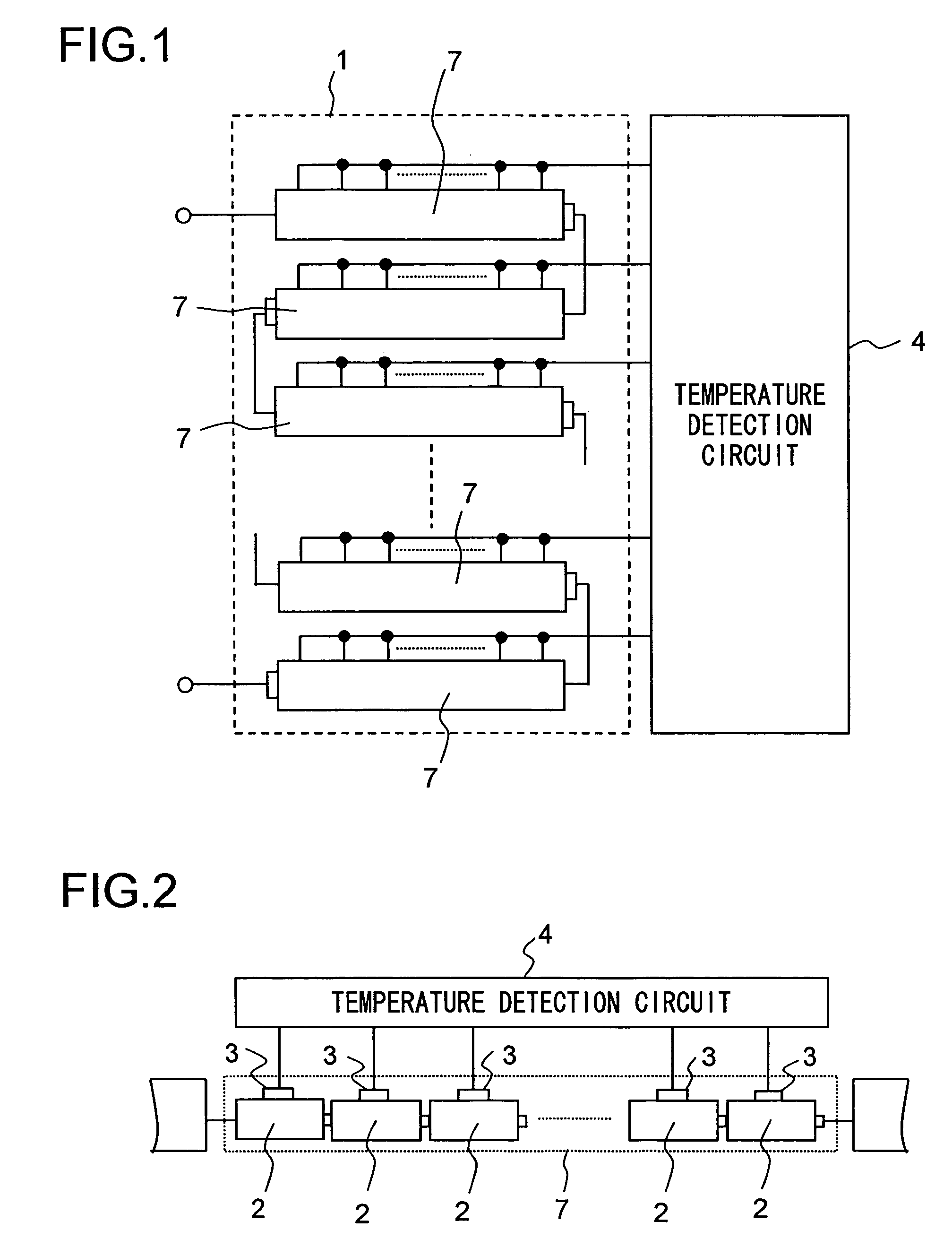
[0036]FIG. 1 is a diagram showing an outline of the circuit design of a power supply apparatus embodying the invention. FIG. 2 is an enlarged view of the battery module 7 shown in FIG. 1...


PUM

PropertyMeasurementUnit
output voltageaaaaaaaaaa
direct-current voltageaaaaaaaaaa
limit currentaaaaaaaaaa

Abstract

A power supply apparatus has a battery apparatus that is composed of a battery, a temperature sensor that is thermally coupled to the battery and whose electrical resistance changes with the temperature of the battery to which it is thermally coupled, a temperature detection circuit that detects the temperature of the battery by detecting the electrical resistance of the temperature sensor, and a power supply circuit that feeds electrical power to the temperature detection circuit. The temperature sensor is connected via an overcurrent protection circuit to the power supply circuit.

Description

[0001] This application is based on Japanese Patent Applications Nos. 2004-101544 and 2005-049246 filed on Mar. 30, 2004 and Feb. 24, 2005, respectively, the contents of which are hereby incorporated by reference. BACKGROUND OF THE INVENTION [0002] 1. Field of the Invention [0003] The present invention relates to a power supply apparatus such as one designed for use in a vehicle to make it run. More particularly, the present invention relates to a power supply apparatus that uses a battery as an electric power source for driving a load and that incorporates a temperature detection circuit for detecting the temperature of the battery. [0004] 2. Description of Related Art [0005] Power supply apparatuses that yield a high output voltage thanks to a plurality of batteries connected in series are used as power supply apparatuses for use in vehicles such as hybrid cars. This type of power supply apparatus incorporates a circuit for detecting the temperature of batteries. When batteries ar...

Claims


Application Information

Patent Timeline
Patent Type & Authority Applications(United States)
IPC IPC(8): H01M2/34G01K7/24H01M6/42H01M10/48H02J7/16
CPCG01K7/24H01M10/486H01M6/42H01M2/348Y02E60/10H01M50/581
Inventor SEO, KAZUHIROFURUKAWA, KIMIHIKO
Owner SANYO ELECTRIC CO LTD
Learn More