
Shielded TEM surface array for parallel imaging

a parallel imaging and shielded technology, applied in the field of magnetic resonance imaging (mri) systems, can solve problems such as the geometry of resonance elements, and achieve the effect of poor circuit coupling

Active Publication Date: 2005-10-20
GE MEDICAL SYST GLOBAL TECH CO LLC
View PDF3 Cites 6 Cited by
  • Summary
  • Abstract
  • Description
  • Claims
  • Application Information

AI Technical Summary

Benefits of technology

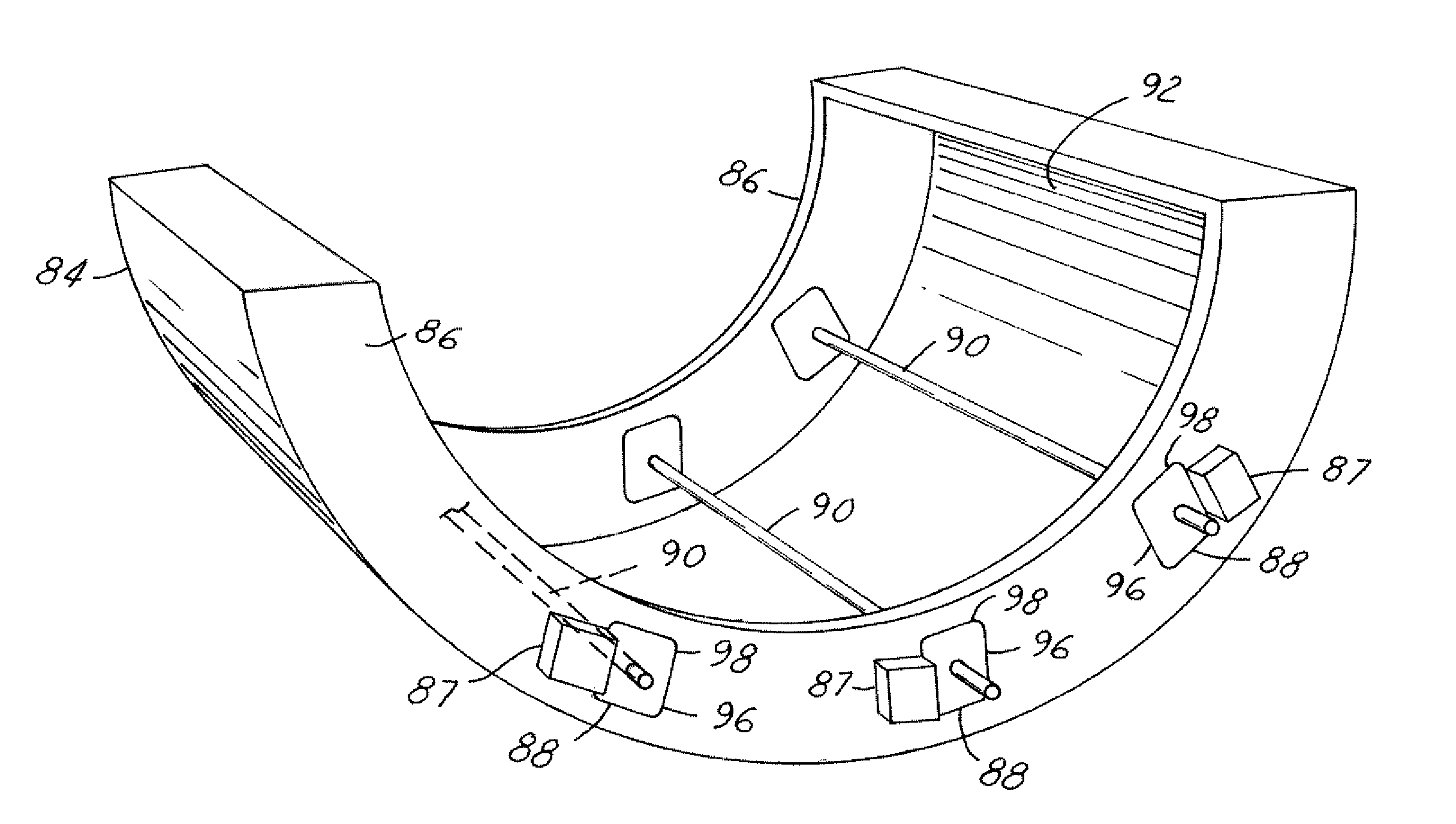
[0016] One advantage of the present invention (as noted above) is that relatively poor circuit coupling (−10 dB between near neighbor elements) is tolerable and will generate useable image reconstructions in parallel imaging. This isolation is achieved within the TEM geometry by the use of conventional means to be described and exemplified. A consequent advantage is that quarter wave elements are not necessary, and therefore the geometric constraints they require need not be imposed. The designer is resultantly allowed to tailor the resonant geometry for optimal coverage of the anatomy or object to be scanned.

Problems solved by technology

The particular requirement for quarter wave elements in TEM arrays is due to the rather strong coupling which exists between the elements and which is not altogether overcome by the blocking circuitry and preamplifier.
This requirement restricts the resonant element geometry in ways that are potentially undesirable, e.g. to achieve quarter wave lumped elements, length and conductor spacing must combine to produce an inductive reactance of 50 ohms.

Method used


Image

  • Shielded TEM surface array for parallel imaging
  • Shielded TEM surface array for parallel imaging
  • Shielded TEM surface array for parallel imaging

Examples


Embodiment Construction

[0023] While the present invention is described with respect to a method for parallel imaging including a shielded TEM array, the present invention may be adapted to parallel imaging within various systems including: those for magnetic resonance spectroscopy systems, and magnetic resonance angiography. The TEM surface resonator is generally applicable to parallel imaging at high fields.

[0024] In the following description, various operating parameters and components are described for one constructed embodiment. These specific parameters and components are included as examples and are not meant to be limiting.

[0025] Also in the following description, a MRI system component may include any one of the following: a superconducting magnet, a superconducting magnet support structure, a gradient magnet assembly, or any other MRI system component known in the art.

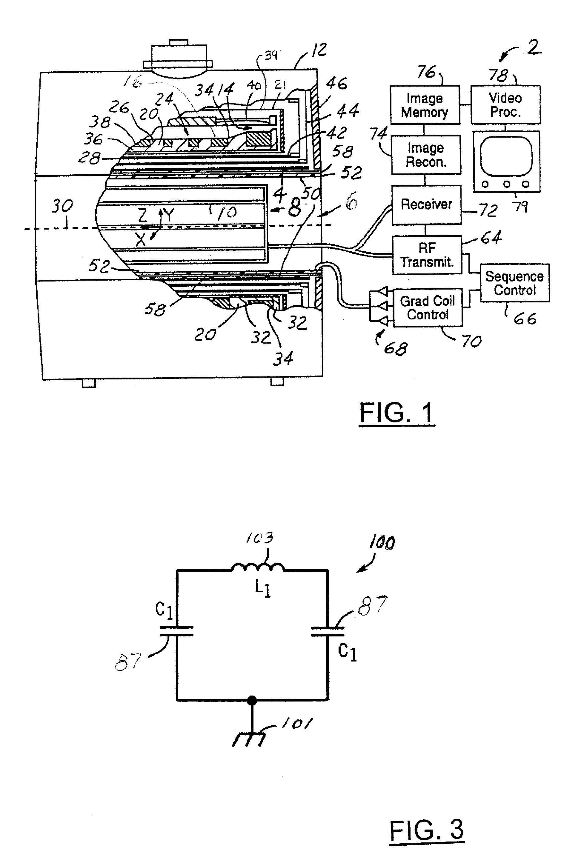
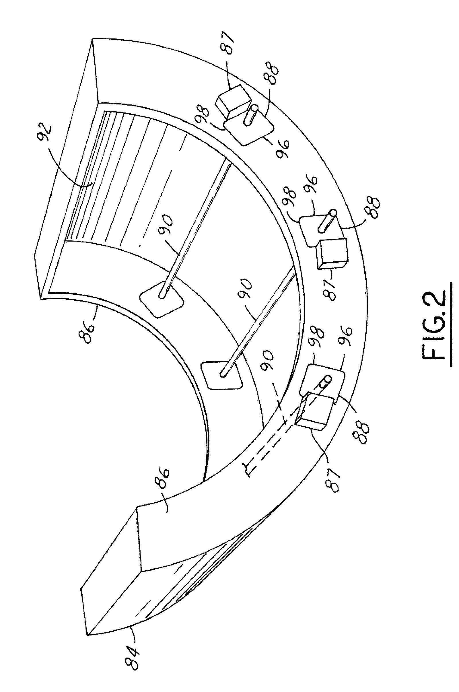
[0026] Referring now to FIG. 1, a block diagrammatic view of a MRI system 2 is shown. The system 2 includes a substantially cyl...


PUM


Abstract

A MRI system having a scanning unit adapted to generate a parallel scan includes a substantially cylindrical member defining a scanning bore and a RF coil assembly mounted in the scanning bore. The RF coil assembly includes a TEM surface resonator.

Description

BACKGROUND OF INVENTION [0001] The present invention relates generally to Magnetic Resonance Imaging (MRI) systems, and more particularly, to a method and system for parallel imaging. [0002] Magnetic Resonance Imaging (MRI) is a well-known medical procedure for obtaining detailed, one, two and three-dimensional images of patients, using the methodology of nuclear magnetic resonance (NMR). MRI is well suited to the visualization of soft tissues and is primarily used for diagnosing disease pathologies and internal injuries. [0003] Typical MRI systems include a superconducting magnet capable of producing a strong, homogenous magnetic field around a patient or portion of the patient; a radio frequency (RF) transmitter and receiver system, including transmitter and receiver coils, also surrounding or impinging upon a portion of the patient; a magnetic gradient coil system also surrounding a portion of the patient; and a computer processing / imaging system, receiving the signals from the r...

Claims


Application Information

Patent Timeline
Patent Type & Authority Applications(United States)
IPC IPC(8): G01R33/34G01V3/00
CPCG01R33/34046G01R33/34007
Inventor TROPP, JAMES S.SODICKSON, M.D., DANIEL K.OHLIGER, MICHAEL A.
Owner GE MEDICAL SYST GLOBAL TECH CO LLC
Learn More