
Planar type ferrite core

Inactive Publication Date: 2005-10-20
TDK CORPARATION
View PDF4 Cites 7 Cited by
  • Summary
  • Abstract
  • Description
  • Claims
  • Application Information

AI Technical Summary

Benefits of technology

[0009] An object of the present invention is to provide a planar type ferrite core able to shorten the overall extended length of a coil, able to reduce the Joule's heat occurring due to the flow of current, enabling mounting of an electronic device at a part of the area gained by reduction of the size of the coil, and enabling a smaller size and higher density of the power supply.
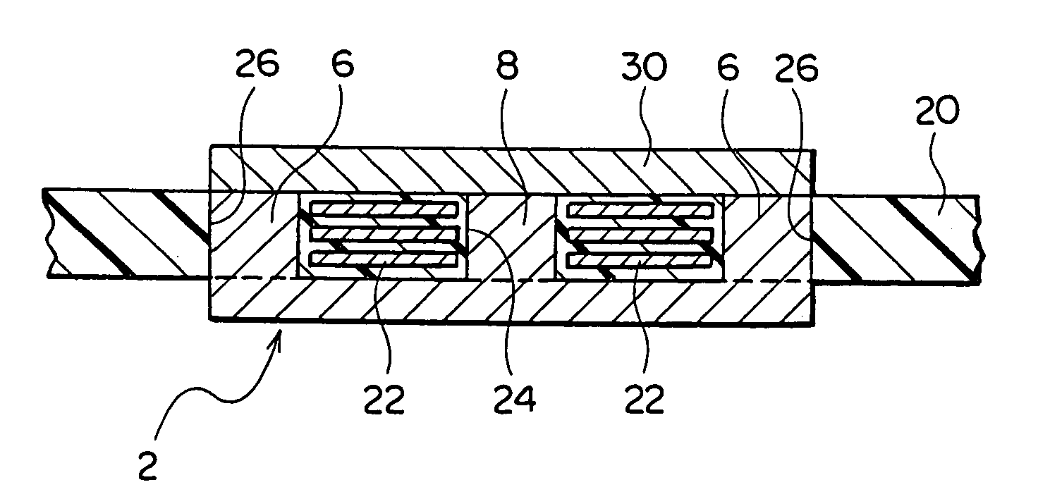
[0011] In the planar type ferrite core according to the present invention, since the two ends of the center leg are formed with arc surfaces of a predetermined radius of curvature, there is no longer any dead space with the coil pattern formed around the center leg. Therefore, the coil pattern can be reduced in size, the overall extended length of the coil can be shortened, and the Joule's heat occurring due to the flow of current can be reduced. Further, another electronic device can be mounted at the part of the area gained by the reduction of the size of the coil and the power supply can be reduced in size and raised in density.
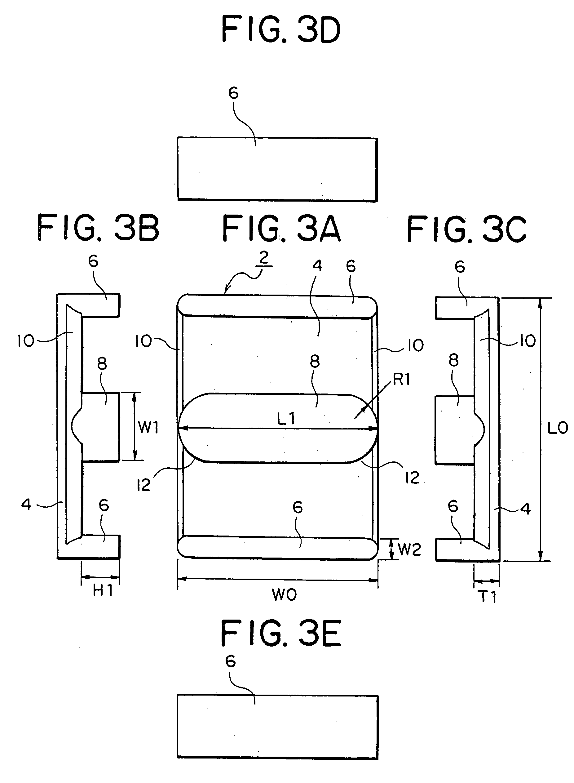
[0012] Further, in the present invention, since the length of the center leg in the longitudinal direction is at least 90% of the width of the flat part, if making the length of the center leg the same as in the past, the width of the flat part can be reduced. As a result, the core as a whole can be made more compact, an electronic device can be mounted at the part of the area gained due to the reduction of the size of the core, and the power supply can be reduced in size and raised in density.
[0013] Preferably, the length of the center leg in the longitudinal direction is substantially the same as the width of the flat part. That is, the length of the center leg in the longitudinal direction is preferably 100% of the width of the flat part. In this case, the action and effect of the present invention are increased.

Problems solved by technology

Therefore, if the two ends of the center leg are right angle surfaces, the coil pattern formed on the board would be wound around the right angle surfaces with great clearance and dead space would result.
In the days when reduction of the size of electronic devices including circuit boards was not demanded that much, these coil patterns did not pose any problem, but as power supplies have been reduced in size, they have come to be considered a problem.
That is, there is fierce competition going on to improve the output current densities of power supplies even incrementally.

Method used


Image

  • Planar type ferrite core
  • Planar type ferrite core
  • Planar type ferrite core

Examples


Embodiment Construction

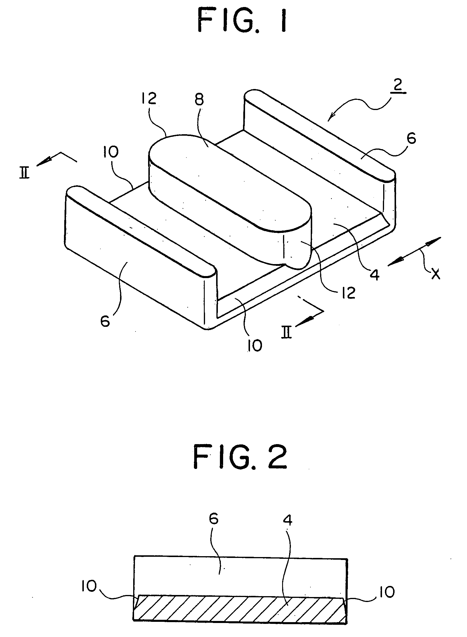
[0025] As shown in FIG. 1, the planar type ferrite core 2 according to an embodiment of the present invention has a rectangular shaped flat part 4. The two ends of this flat part 4 in the longitudinal direction X are integrally formed with a pair of outside legs 6 projecting out from the ends in a direction substantially perpendicular to the plane of the flat part 4.

[0026] A center leg 8 is formed in parallel at a position between the pair of outside legs 6 in the same direction as the outside legs 6 from the plane of the flat part 4. As shown in FIGS. 3A to 3E, a height H1 of the outside legs 6 is the same as a height of the center leg 8. While not particularly limited, it is generally 1 to 10 mm.

[0027] The outside legs 6 are formed along the ends of the flat part 4. Their lengths in their longitudinal directions are the same as a width W0 of the flat part 4. The width W0 of the flat part 4 is not particularly limited, but generally is 5 to 30 mm. Further, a length L0 of the flat...


PUM


Abstract

A planar type ferrite core 2 having a rectangular shaped flat part 4, a pair of outside legs 6 projecting out from two ends of the flat part 4 in a direction substantially perpendicular to a plane of the flat part 4, and a center leg 8 positioned between the pair of outside legs 6 and projecting out from the flat part 4 in the same direction as the outside legs 6, wherein the two ends of the center leg 8 are formed with arc surfaces 12 of a predetermined radius of curvature, and a length L1 of the center leg 8 in the longitudinal direction is at least 90% of a width W0 of the flat part 4. According to the present invention, it is therefore possible to provide a planar type ferrite core able to shorten the overall extended length of a coil, able to reduce the Joule's heat occurring due to the flow of current, enabling mounting of another electronic device at a part of the area gained by reduction of the size of the coil, and enabling a smaller size and higher density of the power supply.

Description

BACKGROUND OF THE INVENTION [0001] 1. Field of the Invention [0002] The present invention relates to a planar type ferrite core to be attached to a coil pattern forming circuit board etc. [0003] 2. Description of the Related Art [0004] Circuit boards are sometimes provided with so-called E-shaped planar type ferrite cores at parts of the circuit boards formed with coil patterns in order to mount transformers, inductors, and other coil devices (for example, see Japanese Patent Publication (A) No. 2003-151838). [0005] An E-shaped planar type ferrite core generally has a rectangular flat part, a pair of outside legs projecting out from the two ends of the flat part in a-direction substantially perpendicular to the plane of the flat part, and a center leg positioned between the pair of outside legs and projecting out from the flat part in the same direction as the outside legs. [0006] In such an E-shaped planar type ferrite core, in the past, the two ends of the center leg in the longit...

Claims


Application Information

Patent Timeline
IPC IPC(8): H01F1/34H01F17/06H01F27/08H01F27/24H01F27/255H01F27/28H05K1/16
CPCH01F27/08H05K1/165H01F2027/2819H01F27/255
Inventor SATO, HIRONORI
Owner TDK CORPARATION
Learn More