Coil for thin-film magnetic head with inductive write head element

a write-head element and thin-film magnetic head technology, which is applied in the direction of instruments, thin material processing, data recording, etc., can solve the problems of no improvement of characteristics, no improvement of magnetic force generated by the coil, and difficulty in writing and reading data operations, etc., to reduce the size reduce the length of the coil conductor itself, and reduce the inductance

Inactive Publication Date: 2005-12-27
SAE MAGNETICS (HK) LTD
View PDF11 Cites 9 Cited by
  • Summary
  • Abstract
  • Description
  • Claims
  • Application Information

AI Technical Summary

Benefits of technology

[0012]It is further preferred that the second sections of turns of the coil conductor are arranged with keeping different spaces from the ABS of the thin-film magnetic head, respectively. In this case, the spaces from the ABS, of the second sections become shorter with distance from the first and second yoke layers. Thus, the length of the coil conductor itself is shortened and the size of the coil conductor is also reduced resulting its inductance to decrease.

Problems solved by technology

If the wave shape of the current flowing through the inductive write head element of the thin-film magnetic head is deformed, magnetic patterns written in a magnetic medium will become distorted and thus write and read operations of data will become difficult.
However, if the number of turns of the coil is reduced to decrease the inductance, magnetic force generated from the coil will decrease causing no improvement of the characteristics.
Also, if the size of the coil is reduced by narrowing a coil pitch, difficulty in fabrication of the coil and problems of heating may occur.

Method used


Image

  • Coil for thin-film magnetic head with inductive write head element
  • Coil for thin-film magnetic head with inductive write head element
  • Coil for thin-film magnetic head with inductive write head element

Examples


Embodiment Construction

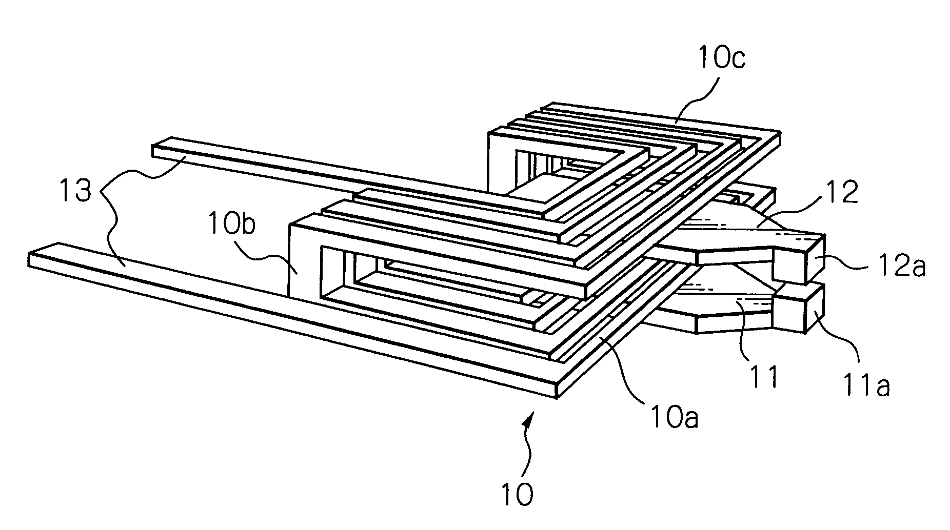
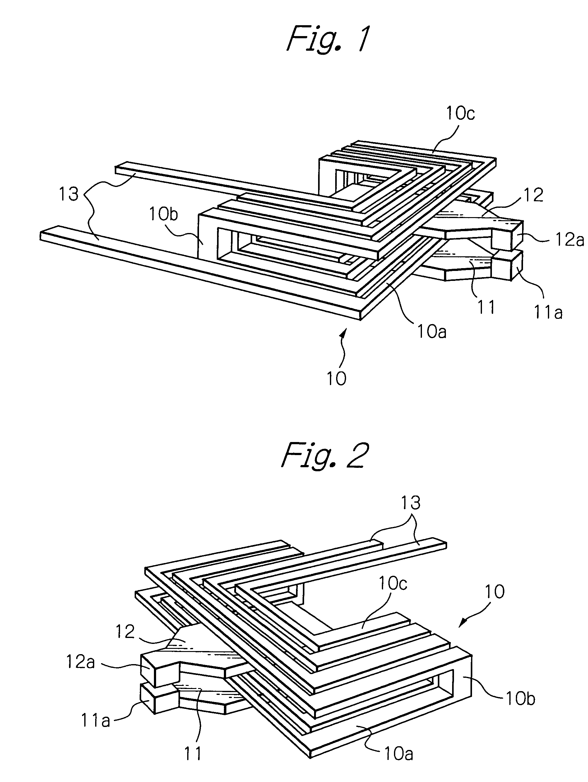
[0022]FIG. 1 illustrates a simple configuration of a coil conductor and yoke layers of a thin-film magnetic head as a preferred embodiment according to the present invention, and FIG. 2 illustrates the same configuration by a view point different from FIG. 1.

[0023]In these figures, reference numeral 10 denotes the coil conductor, made of an electrically conductive material such as copper for example, in a write head element of the thin-film magnetic head, 11 and 12 denote lower and upper yoke layers made of a ferromagnetic material such as permalloy and provided with at its top ends first and second magnetic poles facing each other via an insulation gap and rear ends magnetically coupled with each other, and 13 denotes trace conductors, made of an electrically conductive material such as copper for example, respectively connected to both ends of the coil conductor 10. The coil conductor 10 is illustrated in the figures to have a plurality of turns each wound in a rectangular shape. ...


PUM

PropertyMeasurementUnit
write frequencyaaaaaaaaaa
angleaaaaaaaaaa
magnetic fieldaaaaaaaaaa

Abstract

A thin-film magnetic head includes an insulation gap, first and second yoke layers with first and second ends, respectively, the first ends constituting magnetic poles separated from each other by the insulation gap, the second ends being magnetically coupled with each other, and a coil conductor constituted by a plurality of single layer turns, for generating magnetic field and applying the generated magnetic field into the first and second yoke layers. Each turn of the coil conductor includes a first section, a second section with one end coupled with one end of the first section, and a third section with one end coupled with the other end of the second section. The third section travels to pass outside of the first yoke layer in parallel with the surface of the first yoke layer, and to extend over the first yoke layer.

Description

FIELD OF THE INVENTION[0001]The present invention relates to a thin-film magnetic head element provided with an inductive write head element.DESCRIPTION OF THE RELATED ART[0002]A thin-film magnetic head has a coil wound around a yoke that is magnetically coupled with two magnetic poles separated from each other by a recording gap and performs write operations of magnetic information by following a write current through the coil.[0003]The write current applied to the coil is in general rectangular wave shape pulses. Wave shape and magnitude of current actually flowing through the coil, when the rectangular wave shape pulses are applied vary depending upon the structure of the thin-film magnetic head, upon an output impedance of a current source connected with the coil, and upon a frequency and a voltage of the applied rectangular wave pulses. These are affected also by a characteristic impedance of trace conductors and connection lines between the current source and the magnetic head...

Claims


Application Information

Patent Timeline
Patent Type & Authority Patents(United States)
IPC IPC(8): G11B5/17G11B5/31
CPCG11B5/313G11B5/17Y10T428/11
Inventor KASAJIMA, TAMONSHIRAISHI, MASASHI
Owner SAE MAGNETICS (HK) LTD
Why Eureka
Try Eureka