Centrifuge

a centrifuge and centrifugal technology, applied in the field of centrifuges, can solve the problems of inability to interface directly to a mass spectrometer detector without using a splitter, the speed at which separation may be conducted, and the infancy of separation, so as to increase the number of mixing and settling cycles, the effect of high percentage stationary phase retention

Inactive Publication Date: 2008-08-28
DYNAMIC EXTRACTIONS
View PDF12 Cites 21 Cited by
  • Summary
  • Abstract
  • Description
  • Claims
  • Application Information

AI Technical Summary

Benefits of technology

[0022]In one embodiment, a coil with 0.8 mm internal diameter tubing around 10 metres long was used in the machine able to rotate at high rotational speeds, in excess of 2000 rpm, thus producing a higher “g” level. The effect was to preserve a high percentage stationary phase retention and to increase the number of mixing and settling cycles over a given time period. Both of these effects offset the reduced length of coil tubing.
[0023]The aspect of a cantilevered rotor provided in the machine enables all of the components of the centrifuge to be mounted on the cantilevered rotor and substantially reduced complexity of machine. It also allows the use of specific design features, such as the flying lead configuration, the bobbin configuration and also the enclosed gear box arrangement, all taught herein. It also allows the use of a different type of coil structure as disclosed herein.
[0024]The aspect of the arrangement of a flying lead section reduces to a minimum the number of torturous paths required to be taken by fluid exiting the coil and hence the corruption of the chromatography results. Furthermore, it substantially reduces back pressure and enables the accommodation of back pressure from detection equipment attached to the outlet lead. Furthermore, the simple design of flying lead section can substantially reduce wear and tear thereof and therefore substantially increase the reliability of this component.
[0025]In prior art counter current chromatography instruments, the gear sets have been open, necessarily so by the design of the instruments. This has caused difficulties in lubrication of the gear sets because of the loss of lubricant during use of the machine, the spoiling of the internal casing of centrifuge, making the centrifuge difficult to operate, and also has caused such centrifuges to be noisy in operation. The design of the enclosed gear set taught herein can substantially reduce the above-mentioned problems and can provide for carefully controlled lubrication of the rotor mechanism for a bobbin, thereby providing much more reliable rotation of the bobbin.
[0026]The bobbin structure taught herein enables easy removal of the bobbin, even by the user. Previously, any change of the coils had to be carried out by a service engineer and not by the instrument user. Now, it will be possible for a user to change bobbins, for example to replace an old bobbin with an equivalent new bobbin, and also for a user to have several different designs of bobbin with different coil configurations, thereby enabling a user for the first time to use a single centrifuge for different experimentation.
[0027]Moreover, the preferred design of bobbin taught herein enables an end user to see the ends of the coils, where the stationary phases occur. Such viewing can either be done by the naked eye or by automated optical equipment allowing automated detection and analysis from viewing the coil during operation of the centrifuge. This can provide a very significant advantage in such instruments. For example, a user may wish to include within the mixture being centrifuged optical (such as florescent) markers which become visible during the separation process. Such markers could be detected either by the naked eye or, for example, by a CCD camera and suitable processing software for processing the image from the CCD camera to determine the areas within the coil where the florescent markers become visible.

Problems solved by technology

Although it has been some time since the introduction of counter current chromatography instruments, these still remain in their infancy.
One of the major factors restricting the use of counter current chromatography as an analytical tool is the speed at which a separation may be conducted.
Another problem in the development of such instruments has been the inability to interface directly to a mass spectrometer detector without using a splitter.
This does not provide a sufficiently fast separation for such an instrument to be of significant commercial use.
Separation time can be reduced by reducing the length of the coil but so doing has led to the loss of resolution.
For example, reducing the coil length by a factor of four to reduce capacity to 22.5 ml and separation time down to 45 minutes has only been achievable with a halving of resolution, which is not acceptable.
The conventional coil structures present several difficulties in the design and operation of such centrifuges.
For example, the tubing tends to move and to unwind during operation of the machine.
Although fixing mechanisms such as channels for holding each winding of tubing individually and the use of potting compounds to hold the coils have been used, these do not always prevent the problems and also add complexity and in some cases weight to the machine.
Furthermore, the design of the coil winding tends to be limited to a simple helix arrangement.

Method used


Image

  • Centrifuge
  • Centrifuge
  • Centrifuge

Examples


Embodiment Construction

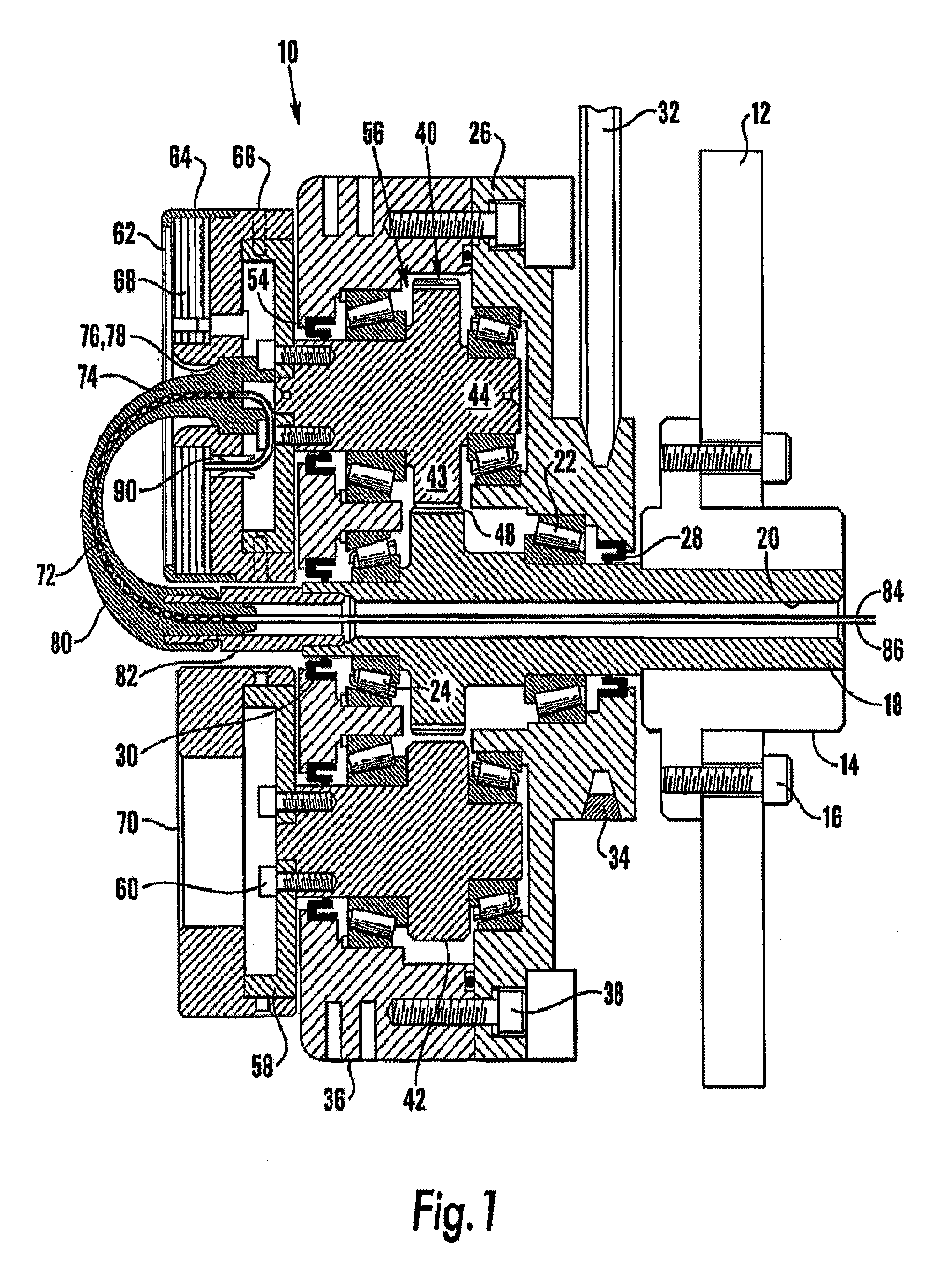
[0039]Referring to FIG. 1, there is shown a preferred embodiment of a “J” type coil planet centrifuge 10 for counter current chromatography (CCC). The centrifuge 10 is intended to be suitable for use with small diameter coils, for example of 1 millimetre internal diameter or less, rotated at high speeds, for example in excess of 2000 rpm. Of course, the size of coil and rotational speeds can be chosen on the basis of the desired application.

[0040]The centrifuge 10 is typically kept in a casing (not shown) for protection purposes and for allowing control of environmental conditions such as temperature. Furthermore, in addition to the components shown in the Figure, the centrifuge 10 is provided with the other elements typical in apparatus of this type, such as power supplies, couplings to mass spectrometer equipment and so on, which will be immediately apparent to the skilled person and thus not described herein in detail.

[0041]The centrifuge 10 includes a support wall 12, in practic...


PUM


Abstract

A centrifuge (10) is provided with improved flying-lead mounting. The centrifuge comprises a cantilevered shaft (18) upon which the main drive rotor (26) is located. A bobbin (62) is attached to the planetary gear shaft (44), which is driven in planetary motion by the rotation of the rotor (26) and its toothed engagement with the shaft (18) of the cantilevered rotor. A flying lead section (72) extends from the bobbin (62) through an aperture in the cantilevered rotor (26) and is provided with a sheath or supporting tube(s) within which at least a portion of inlet and outlet leads are located.

Description

[0001]This application is a Continuation-In-Part of a Continuation U.S. patent application Ser. No. 10 / 958,173, filed Oct. 4, 2004 and claims the benefit of PCT International Application No. PCT / GB03 / 01502, filed Apr. 7, 2003, British Patent Application Nos. 0207959.8, filed Apr. 5, 2002, 0207961.4, filed Apr. 5, 2002, 0207962.2, filed Apr. 5, 2002, and 0207963.0, filed Apr. 5, 2002 which are incorporated by reference herein. The International Application was published in English on Oct. 23, 2003 as WO 03 / 086639 A2 under PCT Article 21(2).TECHNICAL FIELD [0002]The present invention relates to centrifuge apparatus.BACKGROUND ART [0003]Although it has been some time since the introduction of counter current chromatography instruments, these still remain in their infancy. One of the major factors restricting the use of counter current chromatography as an analytical tool is the speed at which a separation may be conducted.[0004]Another problem in the development of such instruments has...

Claims


Application Information

Patent Timeline
Patent Type & Authority Applications(United States)
IPC IPC(8): B04B9/00
CPCB01D15/1807B01D15/1892B04B5/02B04B5/0442G01N30/42B04B9/12B04B15/02B04B2005/0457B04B2005/0492B04B9/08
Inventor HAWES, DAVID WILLIAMJANAWAY, LEESUTHERLAND, IAN ALEXANDERWOOD, PHILIP LESLIE
Owner DYNAMIC EXTRACTIONS
Why Eureka
Try Eureka