CD metrology analysis using a finite difference method

a metrology analysis and finite difference technology, applied in the direction of photomechanical equipment, using wave/particle radiation means, instruments, etc., can solve the problems of rcwa being more than ten times slower, exceedingly slow matrix diagonalization,

Inactive Publication Date: 2005-10-20
THERMA WAVE INC
View PDF12 Cites 7 Cited by
  • Summary
  • Abstract
  • Description
  • Claims
  • Application Information

AI Technical Summary

Benefits of technology

[0016] The modeling method begins with the construction of an idealized representation for the subject being modeled. A numerical method is then used to predict the output field that is created when an incident field is diffracted by the subject. The numerical method begins by computing the output field at the upper boundary of the substrate. In general, the substrate is fabricated using a uniform material. This, combined with the boundary conditions (i.e., that there are only propagating or decaying waves) allows the output field to be computed using and the uniform material that typically makes computation of the resulting output field to be computed directly.

Problems solved by technology

Unfortunately, the exact solutions require repeated matrix diagonalizations in each region in addition to few other matrix operations.
Computationally, matrix diagonalization is exceedingly slow, generally more than ten times slower than other matrix operations such as matrix-matrix multiplications or matrix inversions.
As a result, RCWA tends to be slow, especially for materials with complex dielectric constants.
As the models become more complex (particularly as the profiles of the walls of the features become more complex) the calculations become exceedingly long and complex.
Even with high-speed processors, real time evaluation of these calculations can be difficult.
Amdahl's law also limits the amount of speedup available by parallel processing since serial program portions are not improved.
At the present time, neither cost nor ultimate speed improvement is a serious limitation for parallel processing techniques.
As geometries continue to shrink, however it becomes increasingly possible that computational complexity will outstrip the use of parallel techniques alone.
The use of libraries speeds up the analysis process by allowing theoretical results to be computed once and reused many times. At the same time, library use does not completely solve the calculation bottleneck.
Construction of libraries is time consuming, requiring repeated evaluation of the same time consuming theoretical models.
Process changes and other variables may require periodic library modification or replacement at the cost of still more calculations.
For these reasons, libraries are expensive (in computational terms) to build and to maintain.
Libraries are also necessarily limited in their resolution and can contain only a finite number of theoretical results.
As a result, there are many cases where empirical measurements do not have exact library matches.
This approach avoids the penalty associated with generating results in real time, but sacrifices accuracy during the interpolation process.

Method used


Image

  • CD metrology analysis using a finite difference method
  • CD metrology analysis using a finite difference method
  • CD metrology analysis using a finite difference method

Examples


Embodiment Construction

Theoretical Foundations

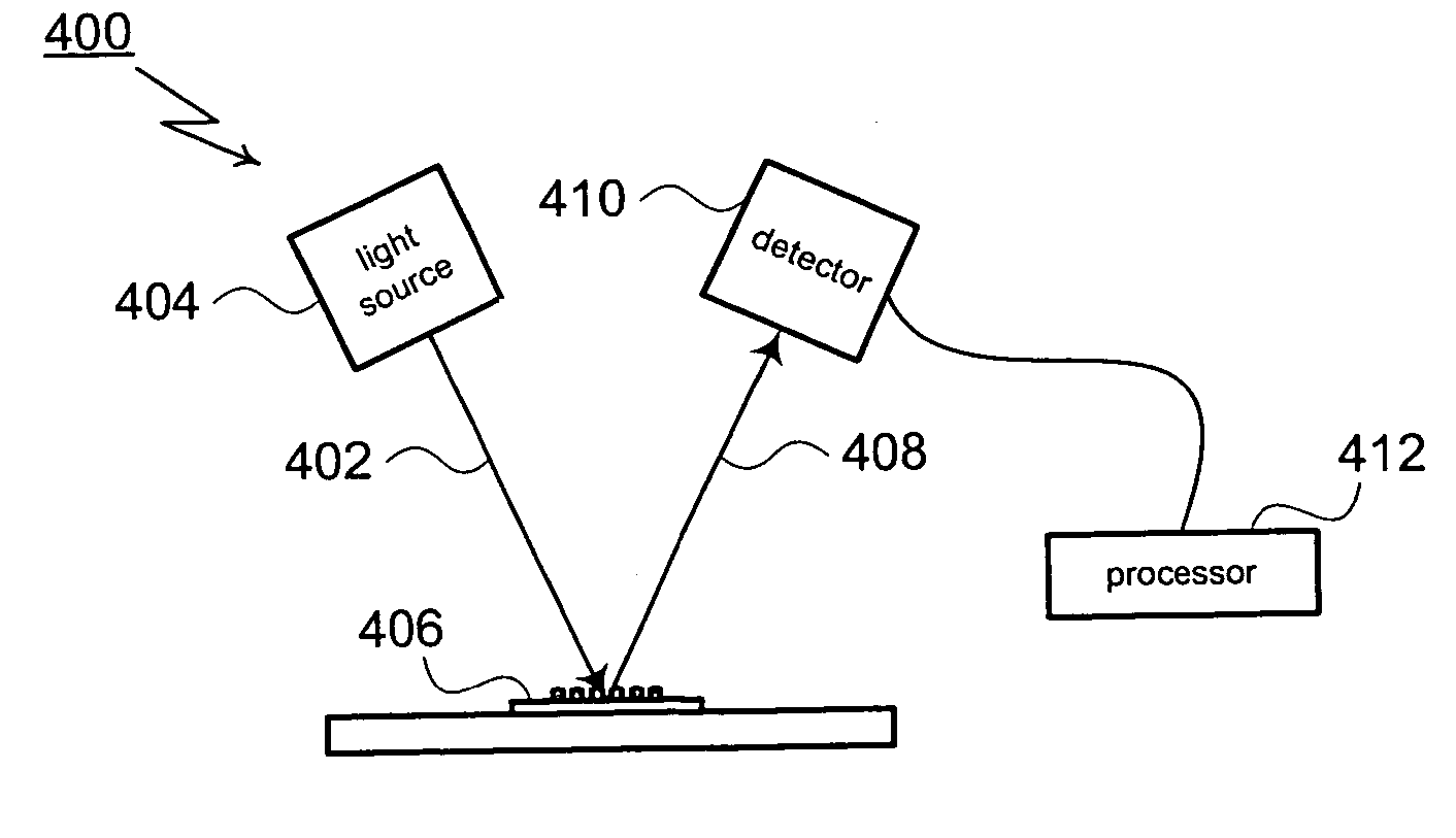
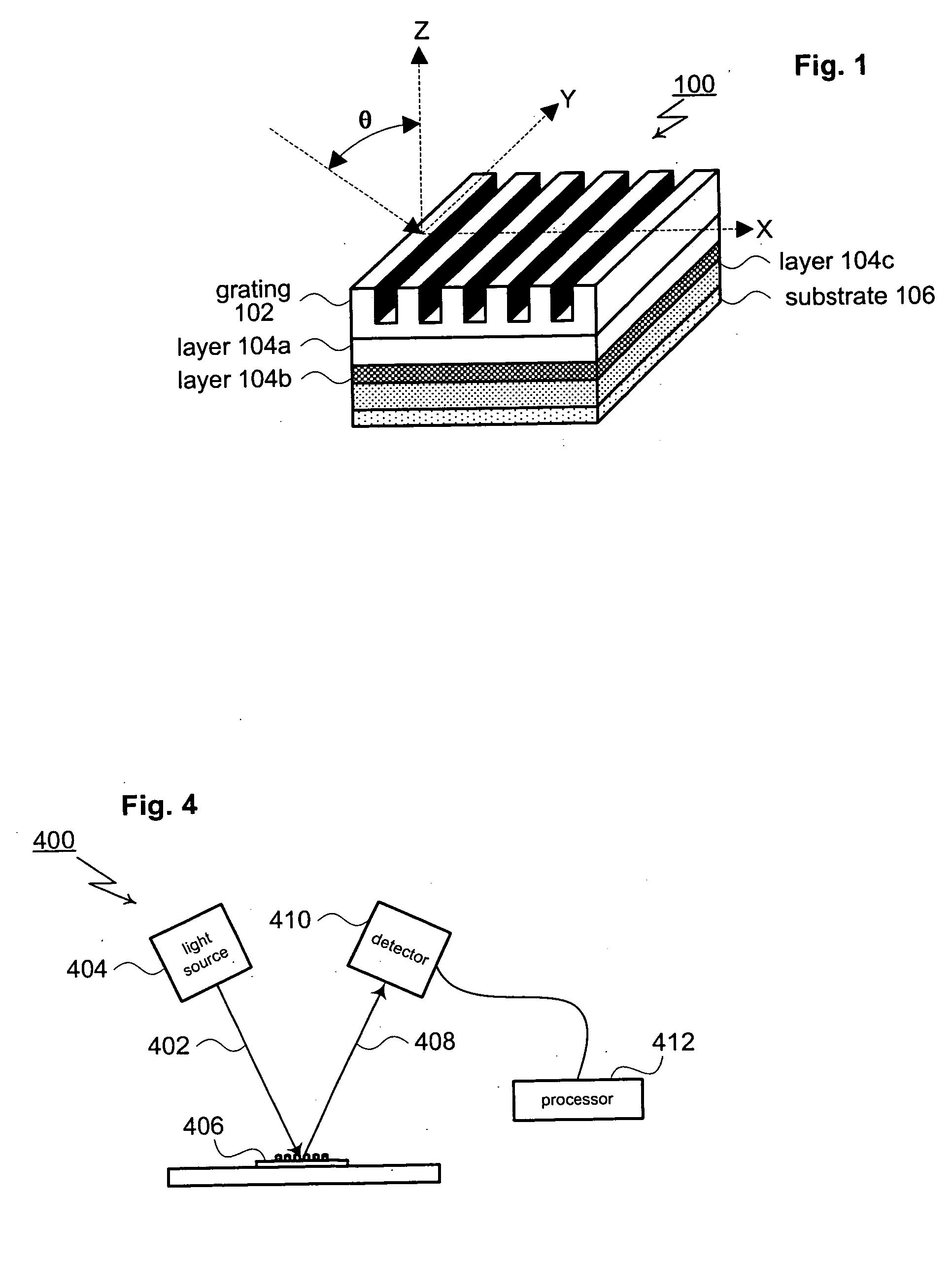
[0023]FIG. 1 shows a generic subject 100 of the type typically analyzed by scatterometry systems. As shown in FIG. 1, the subject 100 includes a surface structure 102. For this particular example, surface structure 102 is a grating formed as a periodic series of lines having a defined profile, width and spacing. The grating is periodic in the X direction and is uniform (exhibits translational symmetry) along the Y axis. In general, surface structure 102 may be formed as a wide range of topologies including isolated or periodic two or three-dimensional structures.

[0024] The subject 100 is covered by an incident medium (not shown) that is typically air but may be vacuum, gas, liquid, or solid (such as an overlaying layer or layers). Below the grating 102, the subject 100 may include one or more layers constructed using one or more different materials. In FIG. 1, the internal layers are labeled 104a through 104c. At the bottom of the internal layers 104, the s...


PUM

PropertyMeasurementUnit
diffracting structureaaaaaaaaaa
reflection coefficientaaaaaaaaaa
field-current ratioaaaaaaaaaa

Abstract

A method for modeling diffraction includes constructing a theoretical model of the subject. A numerical method is then used to predict the output field that is created when an incident field is diffracted by the subject. The numerical method begins by computing the output field at the upper boundary of the substrate and then iterates upward through each of the subject's layers. Structurally simple layers are evaluated directly. More complex layers are discretized into slices. A finite difference scheme is performed for these layers using a recursive expansion of the field-current ratio that starts (or has a base case) at the lowermost slice. The combined evaluation, through all layers, creates a scattering matrix that is evaluated to determine the output field for the subject.

Description

PRIORITY CLAIM [0001] This is a continuation of U.S. patent application Ser. No. 10 / 345,814, filed Jan. 16, 2003, which in turned claims priority to U.S. Provisional Patent Application Ser. No. 60 / 394,542, filed Jul. 9, 2002, the disclosure of which is incorporated herein by reference.TECHNICAL FIELD [0002] The subject invention relates to a technique for numerically determining the scattering response of a periodic structure using a finite difference approach. BACKGROUND OF THE INVENTION [0003] Over the past several years, there has been considerable interest in using optical scatterometry (i.e., optical diffraction) to perform critical dimension (CD) measurements of the lines and structures included in integrated circuits. Optical scatterometry has been used to analyze periodic two-dimensional structures (e.g., line gratings) as well as three-dimensional structures (e.g., patterns of vias or mesas). Scatterometry is also used to perform overlay registration measurements. Overlay m...

Claims


Application Information

Patent Timeline
Patent Type & Authority Applications(United States)
IPC IPC(8): G03F7/20
CPCG03F7/70625
Inventor CHU, HANYOU
Owner THERMA WAVE INC
Why Eureka
Try Eureka