
Method, system and apparatus for interpreting seismic data using duplex waves

a seismic data and duplex wave technology, applied in seismology for waterlogging, instruments, and using reradiation, can solve problems such as the size of an observation surface, and achieve the effect of reducing the effect of any noise and clear imag

Active Publication Date: 2005-10-20
TETRASEIS INC
View PDF12 Cites 17 Cited by
  • Summary
  • Abstract
  • Description
  • Claims
  • Application Information

AI Technical Summary

Benefits of technology

[0015] Advantageously, the method of the present invention based on duplex waves also permits access to both sides of sub-vertical reflectors allowing users to reconcile position calculations from each side of the same sub-vertical reflector based on a single velocity model. If the model is incorrect, then the calculated position of a given sub-vertical reflector may differ based on sources and receivers using energy reflected from opposite sides. Reconciling the positions calculated from each side may occur when the velocity model is incrementally adjusted. As the positions calculated from each side draw closer together (potentially matching for a thin reflector) the velocity model improves to more closely match the sub-surface reality. The improved velocity model is then used to recalculate the position of the “base boundaries” under conventional seismic processing before that information is used in the method and system of the present invention for processing information respecting duplex waves.
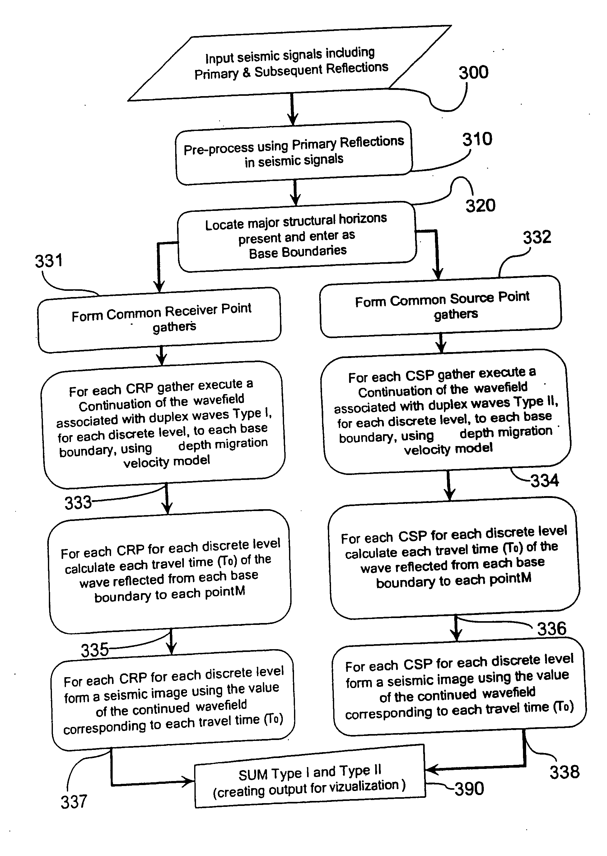
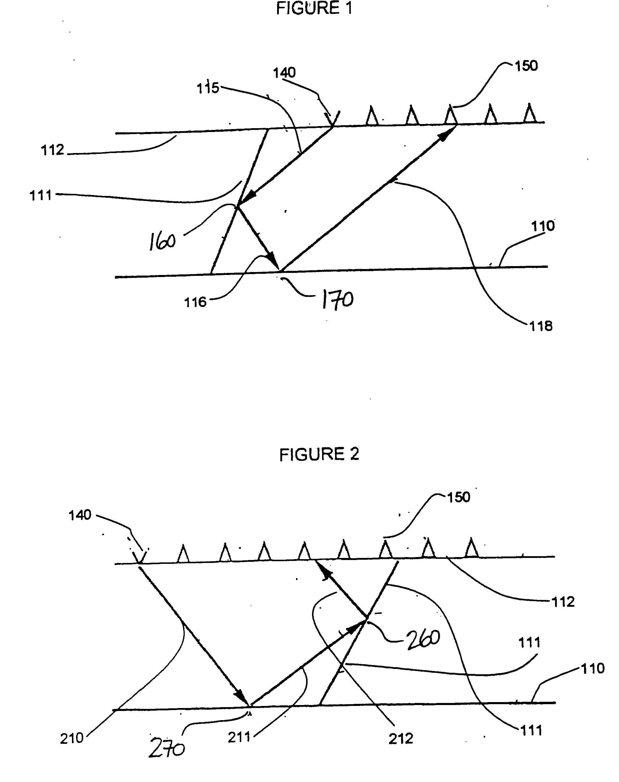
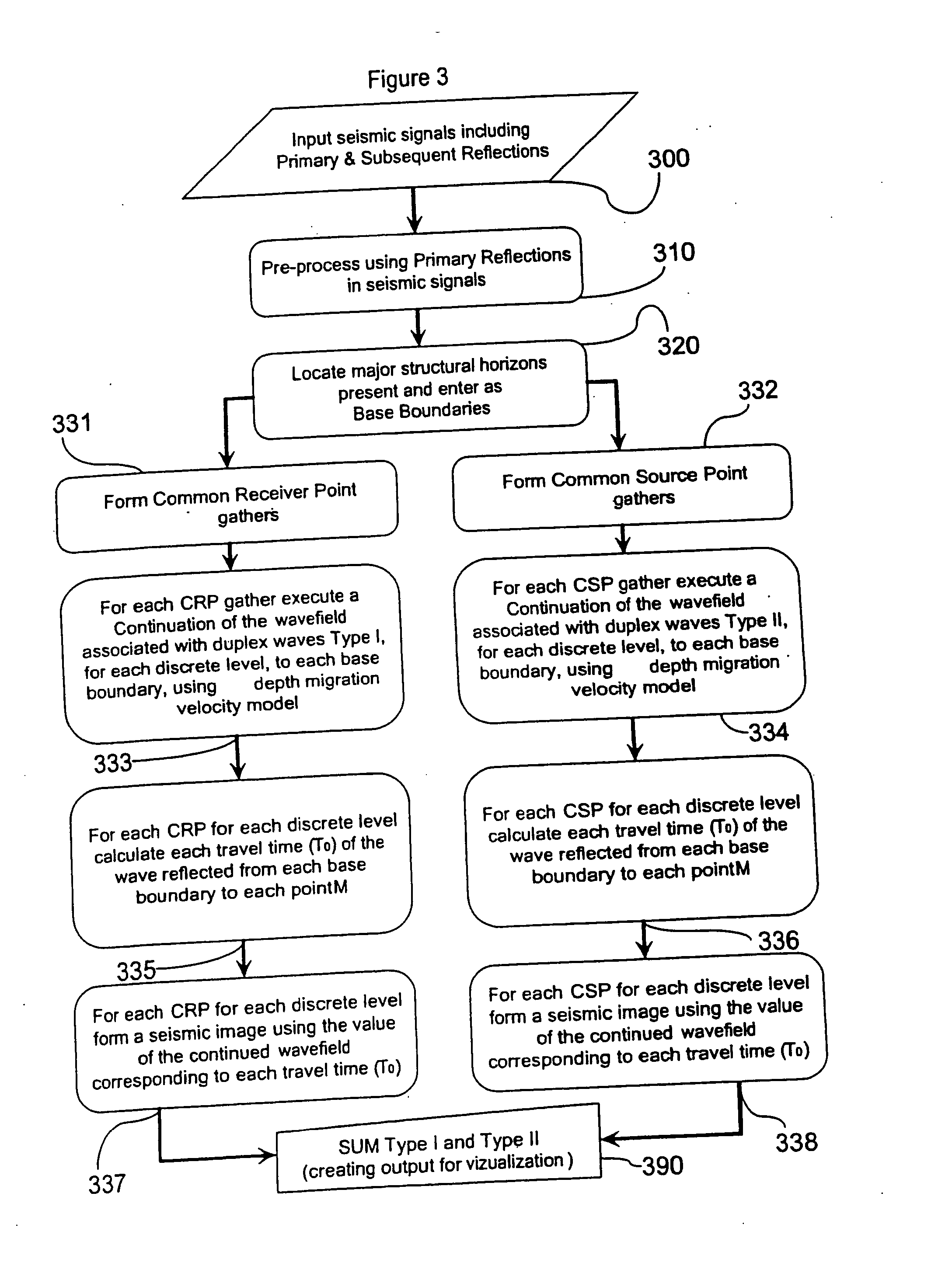
[0016] Advantageously, the method of the present invention does not require any identification of secondary reflections in the data set before applying the inventive migration method. An initial velocity model (i.e. assumptions regarding soil composition) is used to perform migration and obtain position information, variations in which are then used to correct the velocity model and rerun the migration iteratively arriving at images that are consistent between different source / receiver combinations. Using DWM filters or attenuates the effect of all waves that are not based on secondary reflections. Signals from non-duplex waves are stacked out-of-phase such that they are suppressed (in the output) rather than accumulated. Advantageously, a clearer image results in which sub-vertical events can be seen without interference from images relating to horizontal events. The practical limitations of the size of an observation surface are such that primary reflections from sub-vertical events inclined more than 60 degrees do not reach the surface to be recordable within the boundaries of that observation surface. To implement such stacking out-of-phase a person of skill using the DWM method may take advantage of any suitable mathematical technique for continuing a wave field. Duplex waves of two types are captured (when making conventional 2D and 3D seismic observations) as part of each recording. Type I duplex waves are first reflected from a sub-vertical event along the propagation path of the subject wave and then from a sub-horizontal base boundary, before being recorded on an observation surface or line. Type II duplex waves are instead first reflected from a sub-horizontal base boundary and then from a sub-vertical event. Special observation configurations (such as those of 633) are not required because the hodographs of the Types I and II duplex waves (based on secondary reflections) are different than those for primary reflections, but are complementary to each other such that they may be summed either before or after stacking, which reduces the effects of any noise. It is this characteristic of the Types I and II duplex waves that permits the required information to be extracted from data sets gathered using conventional observation systems—without the need of prior information respecting the location and dip extent of steeply dipping sub-verticals. However, if recordings taken from deep inside a borehole (e.g. the VSP method) are also available, the duplex waves captured in those recordings may also be used to form seismic images of such sub-verticals.
[0018] To overcome the disadvantages [e.g. using larger offsets is expensive and the resulting secondary waves are weak] of full wave vector depth migration (theoretically useful to image sub-vertical events) for which the algorithms are also not currently sufficient—advantageously—DWM focuses on vertical events (suppressing information about horizontal events), thereby reducing the total number of bytes of data that must be handled, to make processing very efficient, such that even if one uses a supercomputer to perform full wave vector depth migration, DWM still executes faster even with less computer processor capacity.
[0020] Advantageously, DWM allows summing either or both of Type I and Type II waves, however summing both Types together is preferred because it results in a higher signal / noise ratio.

Problems solved by technology

The practical limitations of the size of an observation surface are such that primary reflections from sub-vertical events inclined more than 60 degrees do not reach the surface to be recordable within the boundaries of that observation surface.

Method used


Image

  • Method, system and apparatus for interpreting seismic data using duplex waves
  • Method, system and apparatus for interpreting seismic data using duplex waves
  • Method, system and apparatus for interpreting seismic data using duplex waves

Examples


Embodiment Construction

[0037] Reference is to be had to FIGS. 1-11 in which identical reference numbers identify similar elements.

[0038] According to the invention, in one of its broad embodiments, there is provided a novel method for using non-primary reflections to accurately identify and characterize steeply dipping sub-vertical events. According to a preferred embodiment of the method of the invention, secondary reflections or duplex waves are migrated while the effects of primary reflections are suppressed. Duplex wave migration uses two types of duplex waves that differ by their direction of propagation. Waves of the first type reflect first from a sub-vertical and then from a sub-horizontal boundary. The second wave type reflects from a sub-horizontal and then a sub-vertical event, before reaching the surface. In duplex wave migration, the main energy contribution is made by waves with large angles of incidence.

[0039] Referring to FIG. 1, a side view of the ray path of a Type I duplex wave is sho...


PUM


Abstract

A Method for Interpreting Seismic Data Using Duplex Waves is described. Whereas substantially horizontal boundaries are readily identified using conventional processing methods based on primary reflections, it has been difficult or impossible to use such methods for locating substantially vertical events or boundaries. The method of the present invention uses secondary reflections to locate substantially vertical events by gathering common source or receiver traces for processing. Wave fields of these gathers are continued downward to the level of the base boundary, then at each discrete depth level, a seismic image of sub-vertical events is formed. The downward-continued gathers correspond to the travel time of the wave from when it left the source or the receiver point, was reflected from the base boundary, and arrived to the corresponding point of the discrete level of wave-field continuation. In order to increase the noise tolerance of the resulting image of the target sub-vertical event—seismic images, obtained from the common source and receiver gathers, may also be summed together or stacked.

Description

RELATED APPLICATIONS [0001] The present application claims priority from U.S. provisional Ser. # 60 / 495,879 filed 19 Aug. 2003.FIELD OF THE INVENTION [0002] The present invention relates generally to processing seismic data and particularly to imaging steeply dipping geologic boundaries. BACKGROUND OF THE INVENTION [0003] Conventional seismic data processing methods are based on detecting primary reflections using a line (2D) or a grid (3D) of receivers placed on or near the surface of a geologic zone of interest. The position of each receiver is known relative to a source of seismic energy, which when triggered creates acoustic mechanical waves, which in turn activate electro-mechanical transducers that are an element of each receiver. Each mechanical wave can activate one or more transducers while outbound from its source, then again upon a first reflection from a subsurface interface or boundary (sometimes called an “event”), and then again upon one or more secondary or tertiary ...

Claims


Application Information

Patent Timeline
IPC IPC(8): G01V1/00G01V1/28
CPCG01V1/28G01V1/301
Inventor MARMALYEVSKYY, NAUMGORNYAK, ZYNOVIY V.KOSTYUKEVYCH, ALEXANDER S.MERSHCHIY, VIKTOR V.ROGANOV, YURIY V.
Owner TETRASEIS INC
Learn More