
Optical disk recorder for writing data with variable density

a technology of optical disk and data recording, applied in the field of optical disk recording method and optical disk recording apparatus, can solve the problem that the optical disk cannot use the density difference of data recording, and achieve the effect of shortening the recording time and reducing the number of recording steps

Inactive Publication Date: 2005-10-20
YAMAHA CORP
View PDF8 Cites 5 Cited by
  • Summary
  • Abstract
  • Description
  • Claims
  • Application Information

AI Technical Summary

Benefits of technology

This approach allows for independent recording operations using different linear densities on the same optical disk, increasing recording capacity and security while maintaining compatibility with existing standards, and enables smooth signal reproduction across varying density zones.

Problems solved by technology

An existing optical disk is incapable of using a data recording density differing from the specification for recording.

Method used


Image

  • Optical disk recorder for writing data with variable density
  • Optical disk recorder for writing data with variable density
  • Optical disk recorder for writing data with variable density

Examples


first embodiment

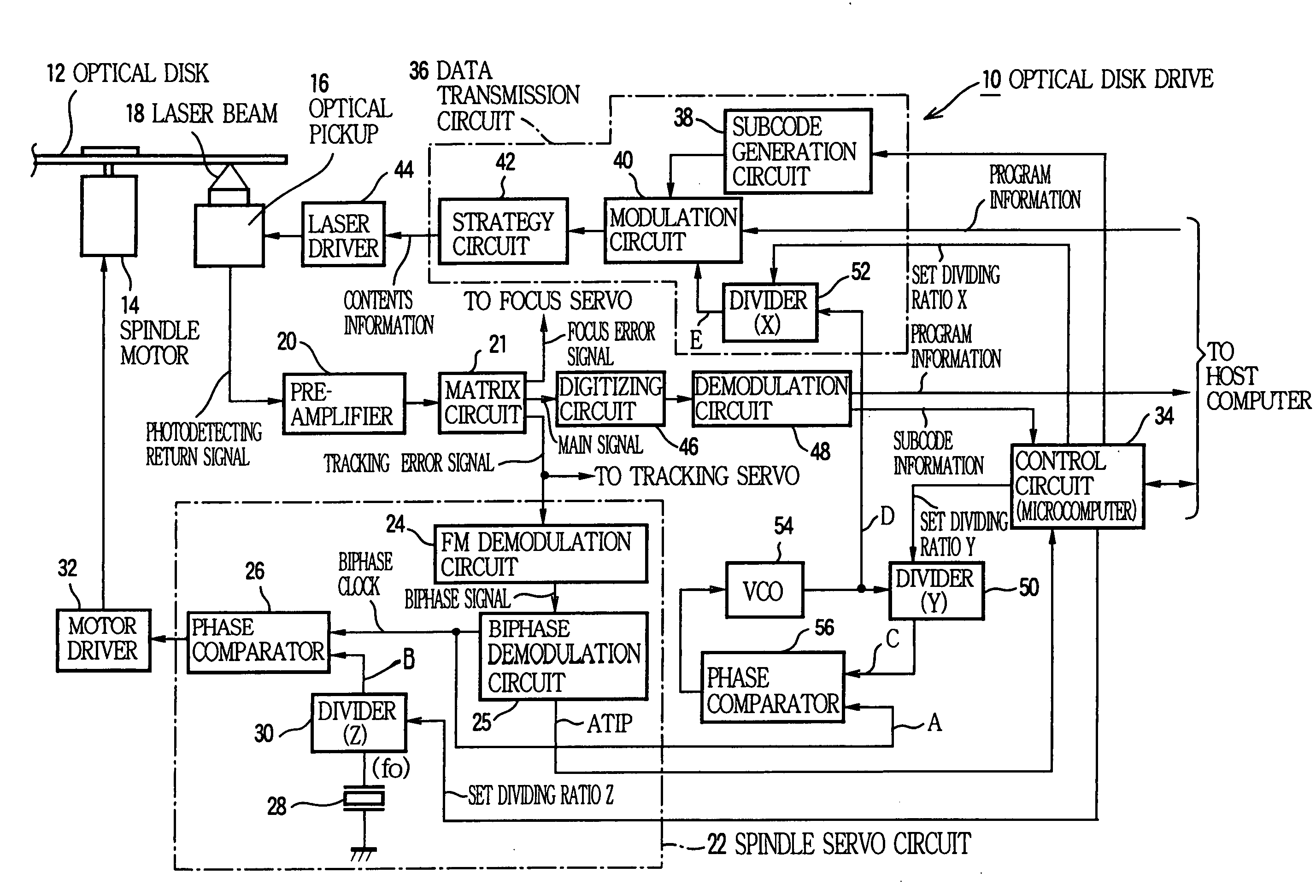
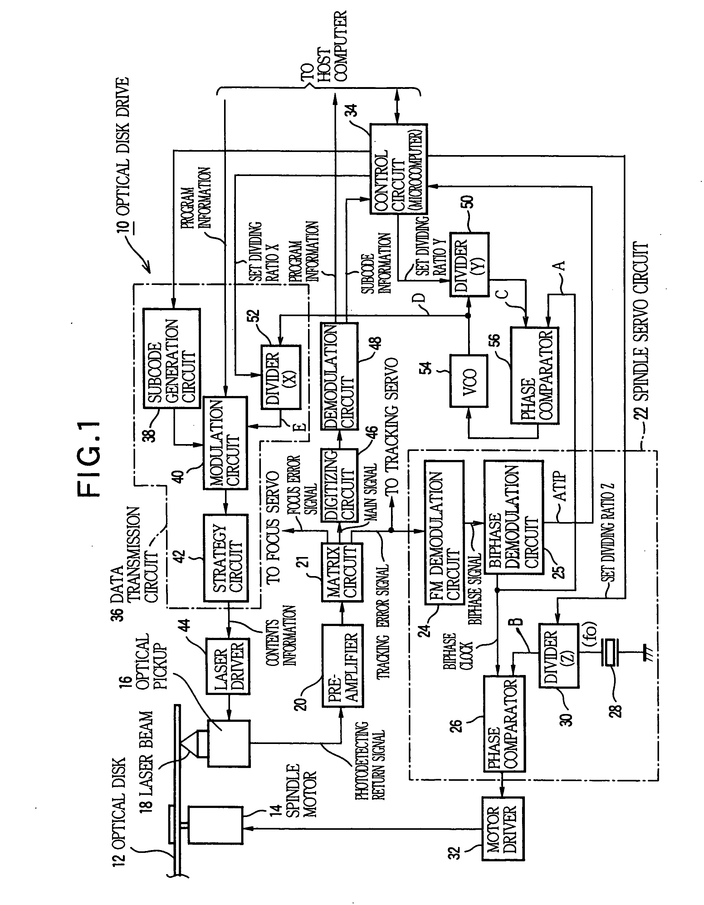
[0041] First embodiment of the present invention is described below. The following describes a case where the present invention is applied to an optical disk drive (CD-R / RW drive) for recording and reproducing of data on CD-R and CD-RW disks. FIG. 1 outlines a system configuration of the optical drive. A optical disk drive 10 is connected to a host computer (not shown). An optical disk 12 is a CD-R or CD-RW disk. A wobbling pre-groove is formed on a recording surface of the optical disk 12. The wobbling is frequency-modulated according to ATIP information.

[0042] A spindle motor 14 rotates the optical disk 12. A laser beam 18 is irradiated from an optical pickup 16 for recording and reproducing information. A photodetecting return signal from each photodetecting element is output from the optical pickup 16 during the recording, and is input to a matrix circuit 21 via a preamplifier 20. The matrix circuit 21 processes the photodetecting return signals from respective photodetecting el...

second embodiment

[0059] Second embodiment of the present invention will be described in further detail with reference to the accompanying drawings. FIG. 3 is a block diagram showing a main configuration of an optical disk recording apparatus according to the present invention.

[0060] The optical disk 101 is provided with a continuous spiral track or substantially circular track from the innermost periphery to the outermost periphery in a recording area. A linear density control signal or index signal is overlapped with this track for ensuring the recording linear density of data to a constant value. In this example, the linear density control signal is a wobble including an ATIP (Absolute Time In Pregroove) time code as absolute time information. While the spindle motor (SPM) 102 rotates the optical disk 101, the wobble signal or index signal is read from the optical disk 101 via the pickup 103, and is supplied to the PLL / wobble decoder 104. The reference clock generator 106 generates a constant refe...


PUM

PropertyMeasurementUnit
frequencyaaaaaaaaaa
frequencyaaaaaaaaaa
clock frequencyaaaaaaaaaa

Abstract

An optical disk recording apparatus operates on an optical disk having circular tracks which are provisionally written with an index signal used for securing a constant linear velocity of the optical disk from an innermost circular track to an outermost circular track, and records data along the circular tracks at different linear densities on different annular zones of the optical disk. In the apparatus, a disk drive section rotates the optical disk while synchronizing the index signal successively read from the rotated optical disk with a predetermined reference clock signal to thereby maintain the constant linear velocity of the circular tracks. A clock generating section multiples or divides the reference clock signal by different rates to generate different writing clock signals in correspondence to the different annular zones of the optical disk. A data recording section operates in synchronization to the different writing clock signals for recording data along the circular tracks at the different linear densities on the different annular zones.

Description

BACKGROUND OF THE INVENTION [0001] The present invention relates to an optical disk recording method and an optical disk recording apparatus for enabling recording of data with recording densities differing from a standard specification of an optical disk to be used. [0002] The present invention also relates to an optical disk recording method and apparatus for recording information on optical disks such as CD-R, CD-RW, CD-WO, MD, DVD, etc. More specifically, the present invention concerns an optical disk recording method and apparatus for dividing a recording area into a plurality of recording zones and for recording data in respective recording zones with different linear densities. [0003] A groove called a pre-groove is formed previously during a course of manufacturing recordable optical disks compliant with CD (compact disk) standards such as a CD-R (CD recordable), a CD-RW (CD rewritable), etc. The pre-groove wobbles. The wobbling frequency is FM-modulated according to absolut...

Claims


Application Information

Patent Timeline
Patent Type & Authority Applications(United States)
IPC IPC(8): G11B7/0045G11B7/007G11B20/12G11B20/14G11B27/19G11B27/24G11B27/30
CPCG11B7/0045G11B2220/2562G11B20/1258G11B20/14G11B20/1403G11B27/034G11B27/24G11B27/30G11B27/3027G11B27/3036G11B27/3063G11B2020/1238G11B2020/1269G11B2020/1292G11B2220/216G11B2220/218G11B2220/2529G11B2220/2545G11B7/0079
Inventor KONAGAI, YUSUKEUSUI, AKIRANOMOTO, KENTARO
Owner YAMAHA CORP
Learn More