Method, apparatus and program for obtaining differential image

a technology of differential image and apparatus, applied in the field of differential image, can solve the problem that the difference between the two images cannot be identified easily

Inactive Publication Date: 2005-10-20
FUJIFILM HLDG CORP +1
View PDF15 Cites 44 Cited by
  • Summary
  • Abstract
  • Description
  • Claims
  • Application Information

AI Technical Summary

Benefits of technology

[0009] The present invention has been developed in view of the circumstances described above, and it is an object of the present invention to provide a differential image obtaining method and apparatus capable of identifying the difference between the X-ray images obtained at different times efficiently. It is a further object of the present invention to provide a program for causing a computer to execute the differential image obtaining method.

Problems solved by technology

In this case, the comparison is made between the image of dilated lung fields and that of the deformed lung fields by the pressure of the heart, and the difference between the two images may not be identified easily.

Method used


Image

  • Method, apparatus and program for obtaining differential image
  • Method, apparatus and program for obtaining differential image
  • Method, apparatus and program for obtaining differential image

Examples


first embodiment

[0097] Hereinafter, the differential image obtaining apparatus will be described with reference to the accompanying drawings.

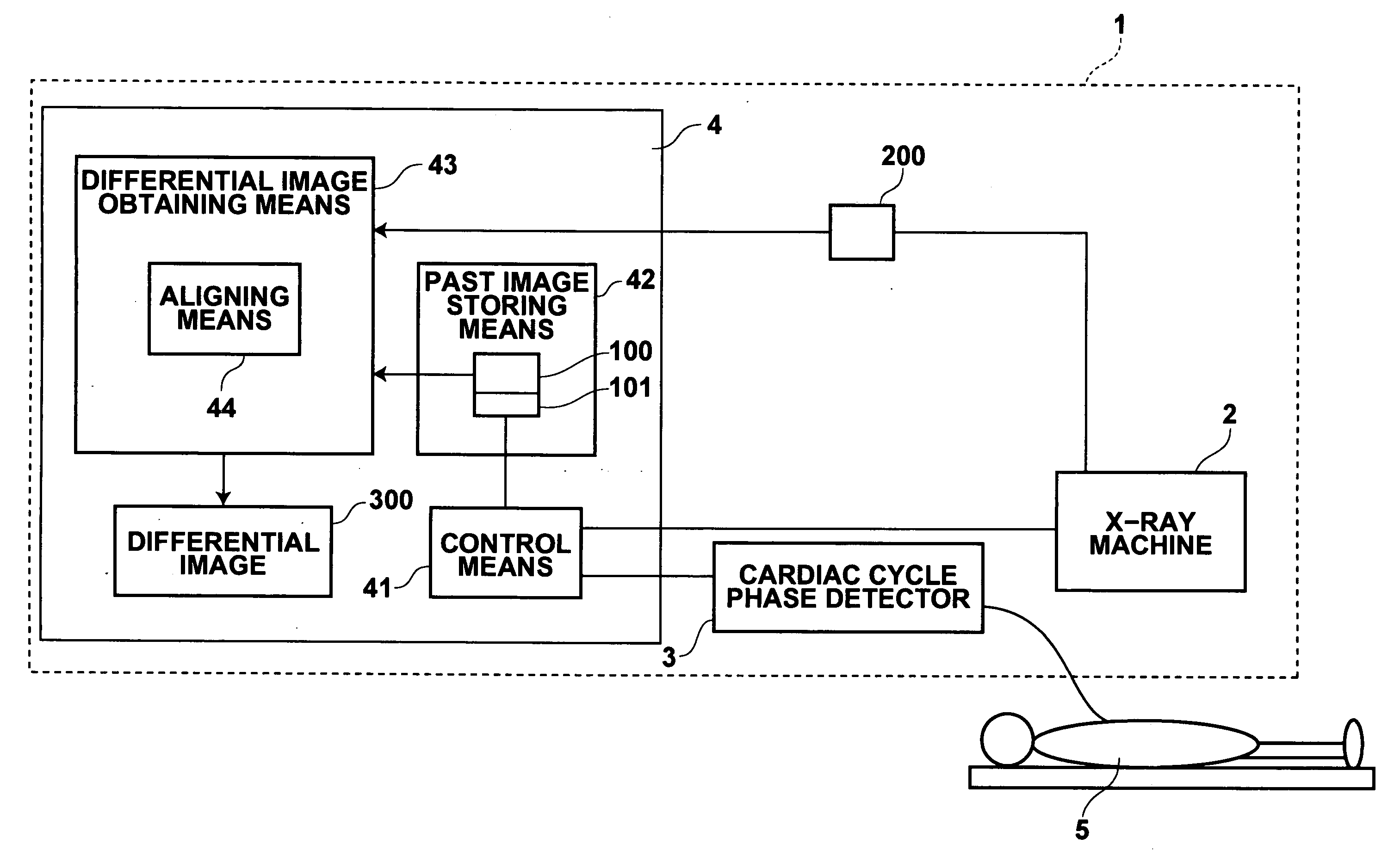
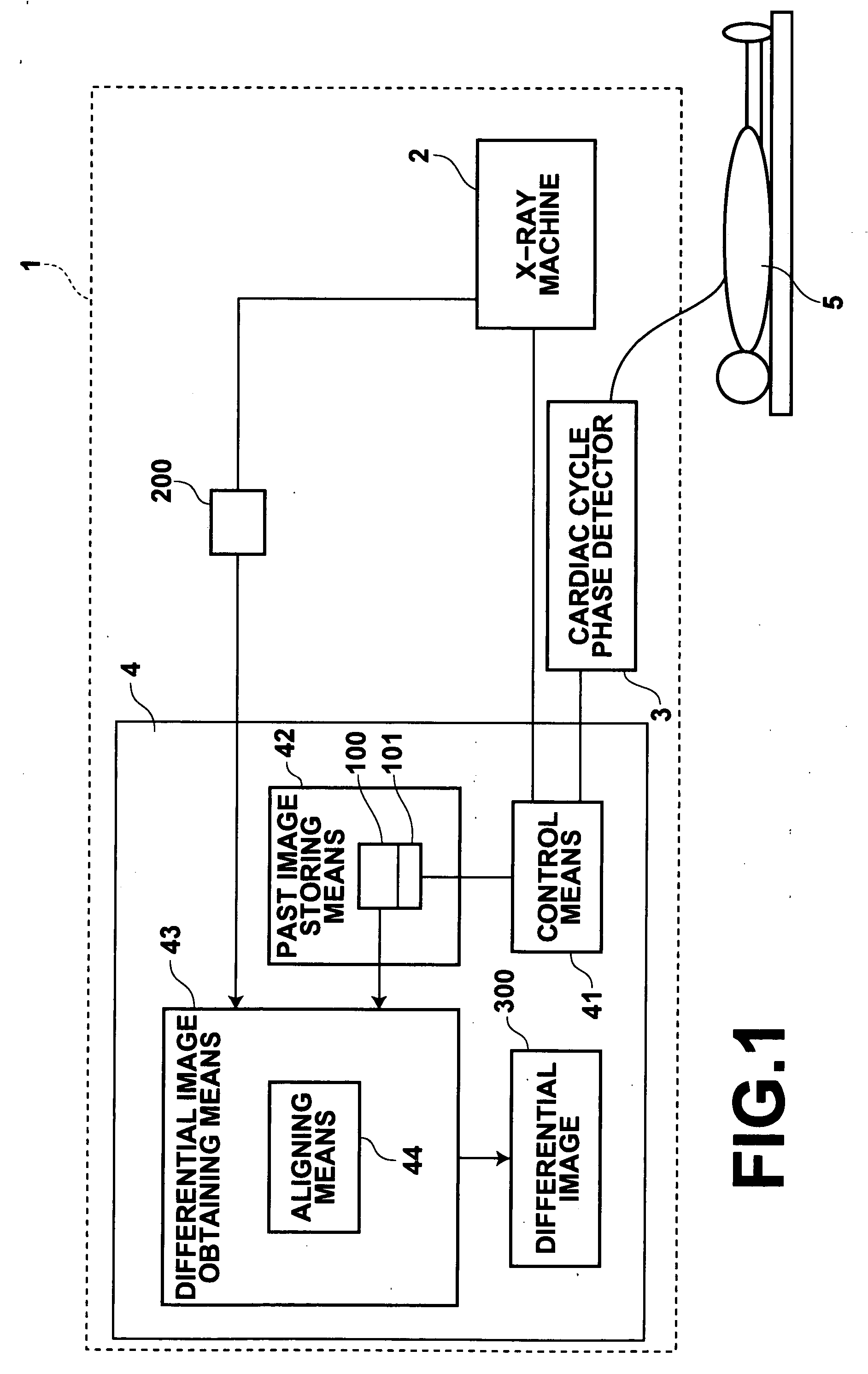
[0098] Now, reference is made to FIG. 1. As shown in FIG. 1, a differential image obtaining apparatus 1 of the present invention comprises: an X-ray machine (radiographing means) 2, such as computed radiography (CR) or the like, for X-raying a subject 5; a cardiac cycle phase detector (cardiac cycle phase detecting means) 3 for detecting cardiac cycle phases of the subject 5; and a computer 4 for controlling the X-ray machine 2 for the timing of imaging.

[0099] The computer 4 has a control means 41 for controlling the X-ray machine 2 for the timing of imaging; a past image storing means 42 for storing a past image 100 obtained by the X-ray machine 2; and a differential image obtaining means 43 for obtaining a differential image 300 from the past image 100 and a current image 200. The differential image obtaining means 43 has an aligning means 44 for aligning ...

second embodiment

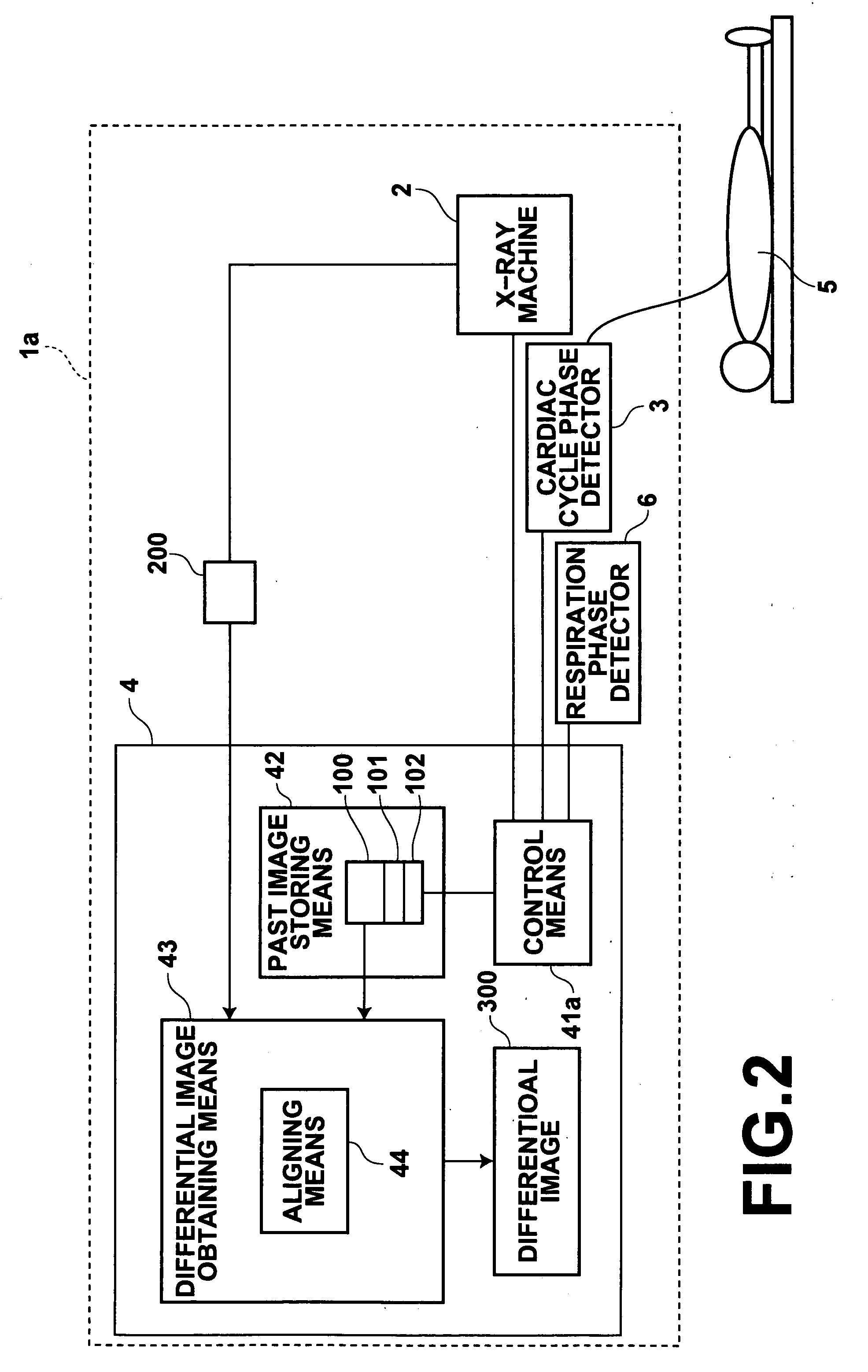
[0124] In the second embodiment described above, the respiration phase detector 6 is used for detecting respiration phases of the subject. But, an alternative arrangement may be made without using the respiration phase detector 6, in which the chest region of the subject 5 is scanned by the X-ray machine 2 with a low radiation dosage to obtain chest X-rays, which are checked in real time, and the respiration phase obtained in this manner is sent to the control means 41a.

[0125] As has been described in detail hereinbefore, the current image is obtained when both the cardiac and respiration phases correspond to those of the past image. Further, the differential image is obtained from the past and current images after the aligning operation has been performed between them. This allows a pale shadow, such as a shadow of lung cancer, may be highlighted even when the chest X-rays are obtained with the subject breathing voluntarily.

[0126] In the first and second embodiments, the differen...

fourth embodiment

[0143] Now, reference is made to FIG. 8. As shown in FIG. 8, a differential image obtaining apparatus 1c according to the present invention comprises the X-ray machine (radiographing means) 2, such as computed radiography (CR) or the like, for X-raying the subject 5; the cardiac cycle phase detector (cardiac cycle phase detecting means) 3 for detecting cardiac cycle phases of the subject 5; the respiration phase detector (respiration phase detecting means) 6 for detecting respiration phases of the subject 5; and the computer 4 for controlling the X-ray machine 2 for the timing of imaging.

[0144] The computer 4 has a control means 41c for controlling the X-ray machine 2 for the timing of imaging; the past image storing means for storing the past image 100 obtained by the X-ray machine 2; and the differential image obtaining means 43 for obtaining the differential image 300 from the past image 100 and current image 200. The differential image obtaining means 43 has a correcting means 4...


PUM


Abstract

Detection of the difference between images of the same subject obtained at different times is performed effectively. The cardiac phases of the subject are detected, and a current image is obtained through X-raying the subject at the time when the detected cardiac phase corresponds to that of the past image. Thereafter, a differential image is obtained from the current and past images by obtaining the difference between them.

Description

BACKGROUND OF THE INVENTION [0001] 1. Field of the Invention [0002] The present invention relates to a method for obtaining images through X-raying a subject and a differential image from the X-ray images obtained. More specifically, the present invention relates to a differential image obtaining method and apparatus for obtaining a differential chest image. It also relates to a program for causing a computer to execute the differential image obtaining method. [0003] 2. Description of the Related Art [0004] In order to monitor the time course of changes in a diseased area through radiographic images, a so-called temporally subtraction technology is proposed as described, for example, in the non-patent document “Digital image subtraction of temporally sequential chest images for detection of interval change”, A. Kano, K. Doi, H. MacMahon, D. Hassell and M. L. Ginger, Med. Phys. 21(3), March 1994, pp. 453-461. The technology is used to generate a differential image from temporally seq...

Claims


Application Information

Patent Timeline
Patent Type & Authority Applications(United States)
IPC IPC(8): A61B5/05A61B6/00A61B6/06H04N5/325
CPCA61B6/503A61B6/4291A61B6/541
Inventor SENDAI, TOMONARI
Owner FUJIFILM HLDG CORP
Why Eureka
Try Eureka