Integrated dehumidification system

a dehumidification system and integrated technology, applied in the field of integrated dehumidification systems, can solve the problems of limiting latent cooling capacity, failure to control excessive indoor humidity, and often requiring more dehumidification of air, so as to achieve convenient installation, maintain indoor air quality, and efficiently and effectively dehumidify outside ventilation air

Inactive Publication Date: 2005-10-27
DAVIS ENERGY GROUP
View PDF24 Cites 48 Cited by
  • Summary
  • Abstract
  • Description
  • Claims
  • Application Information

AI Technical Summary

Benefits of technology

[0016] In various exemplary embodiments, the systems and methods of this invention efficiently and effectively dehumidifies outside ventilation air supplied to buildings for the purpose of maintaining indoor air quality.
[0017] In various exemplary embodiments, the systems and methods of this invention combines indoor cooling and dehumidification components into a single unit to facilitate installation and reduce cost.

Problems solved by technology

In humid climates the ventilation air often requires more dehumidification than can typically be provided by air conditioners, because typical air conditioners in energy-efficient homes have short run times during many cooling load hours.
Short run times typically limit latent cooling capacity.
Failure to control excessive indoor humidity has contributed to problems with indoor mold.
This issue has become increasingly expensive for homeowners and builders, as mold-related property damage and class action lawsuits have risen steadily.
Some vapor compression cooling systems lower the airflow rate through the evaporator coil to reduce the SHR under humid conditions, but re-evaporation of condensate retained on the coil at system shutdown still limits the SHR, particularly when systems cycle frequently, as they do under low load conditions.
Because heat from the condenser is added to indoor air, the dehumidifier often increases the sensible cooling load, the air conditioner run time, and the amount of energy consumption.
However, all heat from the second loop is added to the supply air, with associated energy penalties.
This approach adds substantial cost to a conventional system with a single refrigerant loop.
This design selectively causes a portion of the return air to bypass the evaporator coil, which lowers the coil temperature and increases moisture condensation on the coil.
However, this approach is unlikely to succeed in the market, as it is comparable to lowering the blower speed, but with higher initial costs and without the energy savings associated with reducing blower speed.
However, the economics of such a system will be poor because gas water heating is substituted for waste heat already available from the condensing side of the refrigerant system.
These designs require added components to recharge the desiccant and therefore may not be cost-effective.
However, both products can only control humidity by varying fan and compressor speed.
There are no added components designed to respond to conditions with high humidity and low cooling loads.
Thus, these systems cannot maintain a specified temperature / humidity set through a wide range of conditions.
Adding more length to the coil on the condenser side also reduces the liquid refrigerant temperature into the evaporator, which increases evaporator capacity and therefore drops the evaporator temperature, increasing the rate of moisture removal.
In fact, the Lennox™ hot gas approach is only workable in a single package device, as the system would require an extra pair of refrigerant lines to be applied in a “split system” configuration because refrigerant must flow first to the indoor reheat coil, then back to the condenser, then to the indoor expansion device.
However, the approach only provides two stages of dehumidification, and therefore cannot sufficiently control humidity when sensible loads are very low and latent loads are high.
Although the vapor compression systems disclosed above, and others, use hot gas and sub-cooling reheat coils to reduce the SHR in single-package units, no known systems dynamically combine features that, by applying multiple dehumidification stages in a split system configuration, can maintain desired temperature and humidity conditions even in the absence of cooling loads, through the full range of climatic conditions in the U.S. and elsewhere.

Method used


Image

  • Integrated dehumidification system
  • Integrated dehumidification system
  • Integrated dehumidification system

Examples


Embodiment Construction

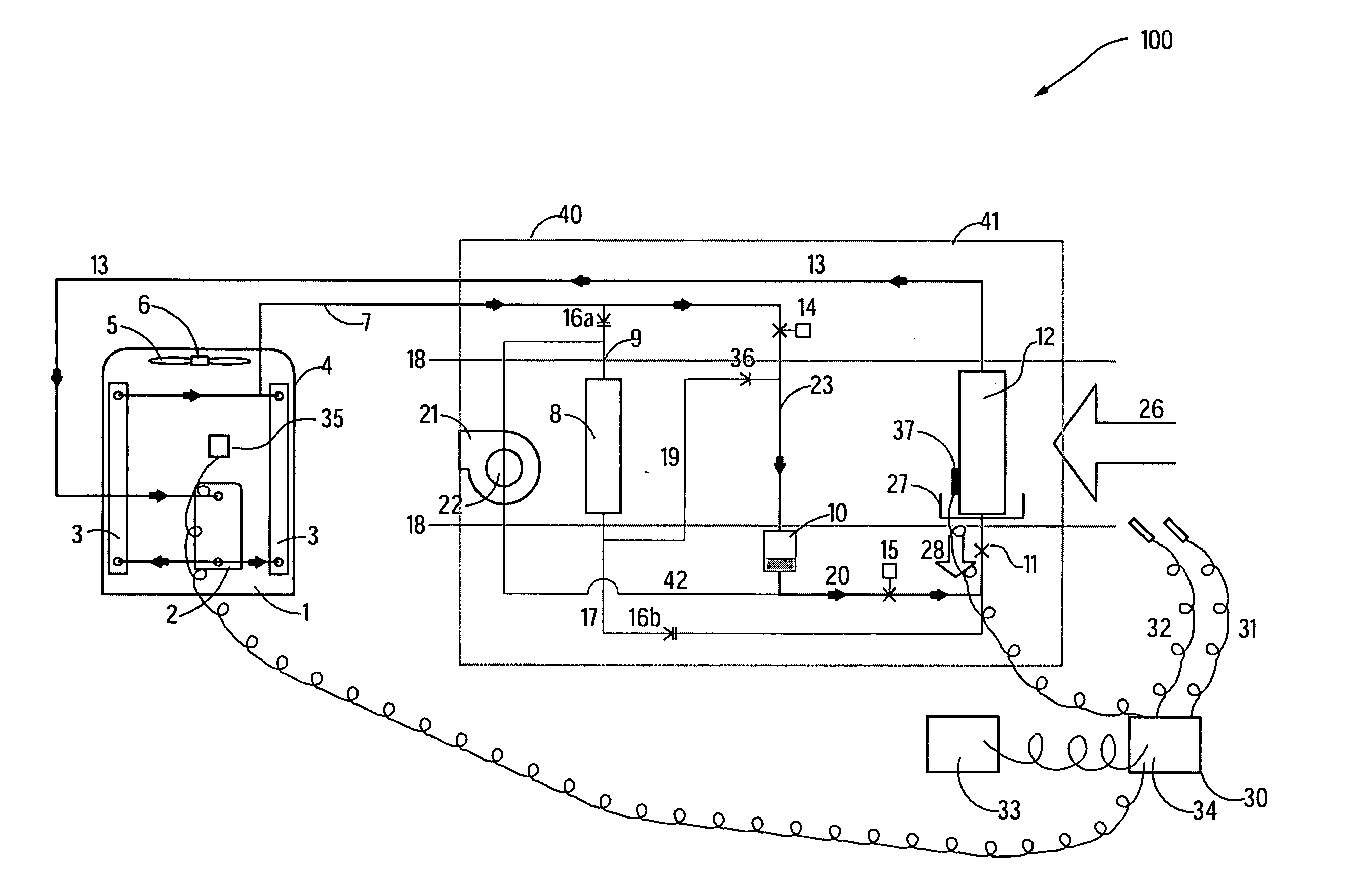
[0023] An exemplary embodiment of the systems and methods described in this disclosure comprises a set of vapor compression cooling components that can respond to a wide range of sensible and latent cooling loads, and control components with appropriate logic for automatically maintaining indoor temperature and relative humidity within close tolerances. The embodiment can condition either re-circulated indoor air, outside ventilation air supplied to buildings to maintain indoor air quality, or a mixture of the two. Exemplary components of such a system include a compressor, a condensing coil, a condenser fan, an indoor blower, an evaporator coil, a reheat coil, a refrigerant receiver, a thermostatic expansion valve, solenoid valves for switching refrigerant flow, a check valve, “pressure-differential check valves” (PDCV's), temperature and humidity sensors, and controls for selecting an operating mode based on sensed conditions.

[0024] With reference to FIG. 1, an integrated dehumid...


PUM


Abstract

A dynamic system controls indoor relative humidity and temperature to achieve specified conditions by applying multiple stages of dehumidification. In addition to an optional stage that increases dehumidification by reducing the speed of the indoor blower, the system uses a reheat coil and multiple valves that allow the reheat coil to function as either a subcooling coil or a partial condenser. Thus the system can maintain specified indoor temperature and humidity conditions even at times when no heating or cooling is needed. The system may have an outdoor condensing unit including a compressor and a condenser operably connected via refrigerant lines to an indoor unit to form a “split system” refrigerant loop.

Description

CROSS-REFERENCE TO RELATED APPLICATION [0001] This application claims the benefit of U.S. Provisional Application No. 60 / 565,532, filed on Apr. 27, 2004.BACKGROUND [0002] The subject matter of this disclosure relates to providing building cooling, dehumidification, and fresh air ventilation through a range of outdoor and indoor conditions. [0003] New U.S. homes that are built in compliance with ASHRAE Standard 90.2, Energy Star, and other energy efficiency programs have lower cooling loads than in the past, and because they are of tighter construction, they frequently require mechanical ventilation as prescribed by ASHRAE Standard 62.2. In humid climates the ventilation air often requires more dehumidification than can typically be provided by air conditioners, because typical air conditioners in energy-efficient homes have short run times during many cooling load hours. Short run times typically limit latent cooling capacity. Failure to control excessive indoor humidity has contrib...

Claims


Application Information

Patent Timeline
Patent Type & Authority Applications(United States)
IPC IPC(8): F24F3/153F25B40/02F25B41/00F25D17/04F25D17/06
CPCF25B40/02F24F3/153
Inventor SPRINGER, DAVID A.HOESCHELE, MARC A.BERMAN, MARK J.PHILLIPS, JAMES H.
Owner DAVIS ENERGY GROUP
Why Eureka
Try Eureka