Plasma etching apparatus and plasma etching method

a technology of etching apparatus and plasma, which is applied in the direction of electrical apparatus, basic electric elements, electric discharge tubes, etc., can solve the problems of difficult control in the aforementioned low temperature zone, and achieve the effect of reducing the frequency of part exchange of the inner wall surface, reducing the running cost, and comparatively easy realization

Inactive Publication Date: 2005-10-27
MASUDA TOSHIO +4
View PDF20 Cites 17 Cited by
  • Summary
  • Abstract
  • Description
  • Claims
  • Application Information

AI Technical Summary

Benefits of technology

[0032] According to the present invention, a part of processing gas is polymerized by plasma discharge and a surface coating layer is formed by polymer on the part of the inner wall of the processing chamber which is in contact with plasma or the surface of the part. By controlling the temperature of the inner wall surface of the reactor to a constant temperature sufficiently lower than that of a wafer, the polymerization of the coating layer proceeds and a solid layer structure can be formed. Therefore, the inner wall surface will not be etched and consumed by plasma, so that the frequency of part exchange of the inner wall surface can be reduced and the running cost can be decreased. Even if the coating layer is exposed to plasma, peeling and damage are not caused to the surface thereof because the film composition is dense, so that dust will not be caused.
[0033] Since the temperature of the inner wall surface is set in a temperature zone lower than that of a wafer, as compared with a case that the temperature of the inner wall surface is set in a high temperature zone of 200° C. or more, the interaction between plasma and the inner wall surface is weak and not sensitive to a change in temperature. As a result, the reproducibility and reliability of the process hardly reduce for a long period of time and the accuracy of temperature control may be, for example, less than ±10° C. and can be realized comparatively easily without using a complicated mechanism for temperature control.
[0034] When a polymerized film exceeding a predetermined value is formed on the inner wall surface, it is necessary to remove this film. When the equipment is exposed to the air, and the component part of the inner wall surface of the processing chamber on which the polymerized film is formed is exchanged, and the equipment is reoperated, and the film is removed by wet cleaning on an ex-situ basis after removal from the chamber instead of plasma cleaning, and the inner wall surface is reproduced, satisfactory results can be produced such that the non-operation time of the equipment is reduced, and the throughput is prevented from reduction, and the cost of expendable supplies can be reduced by reproduction and repetitive use of parts. When a process of controlling the growth of the polymerized film is added to the process, the time up to opening and cleaning of the equipment can be prolonged.
[0035] On the

Problems solved by technology

On the other hand, in the reactor, there is a part or a component part w

Method used


Image

  • Plasma etching apparatus and plasma etching method
  • Plasma etching apparatus and plasma etching method
  • Plasma etching apparatus and plasma etching method

Examples


Embodiment Construction

[0046] The embodiments of the present invention will be explained hereunder with reference to the accompanying drawings.

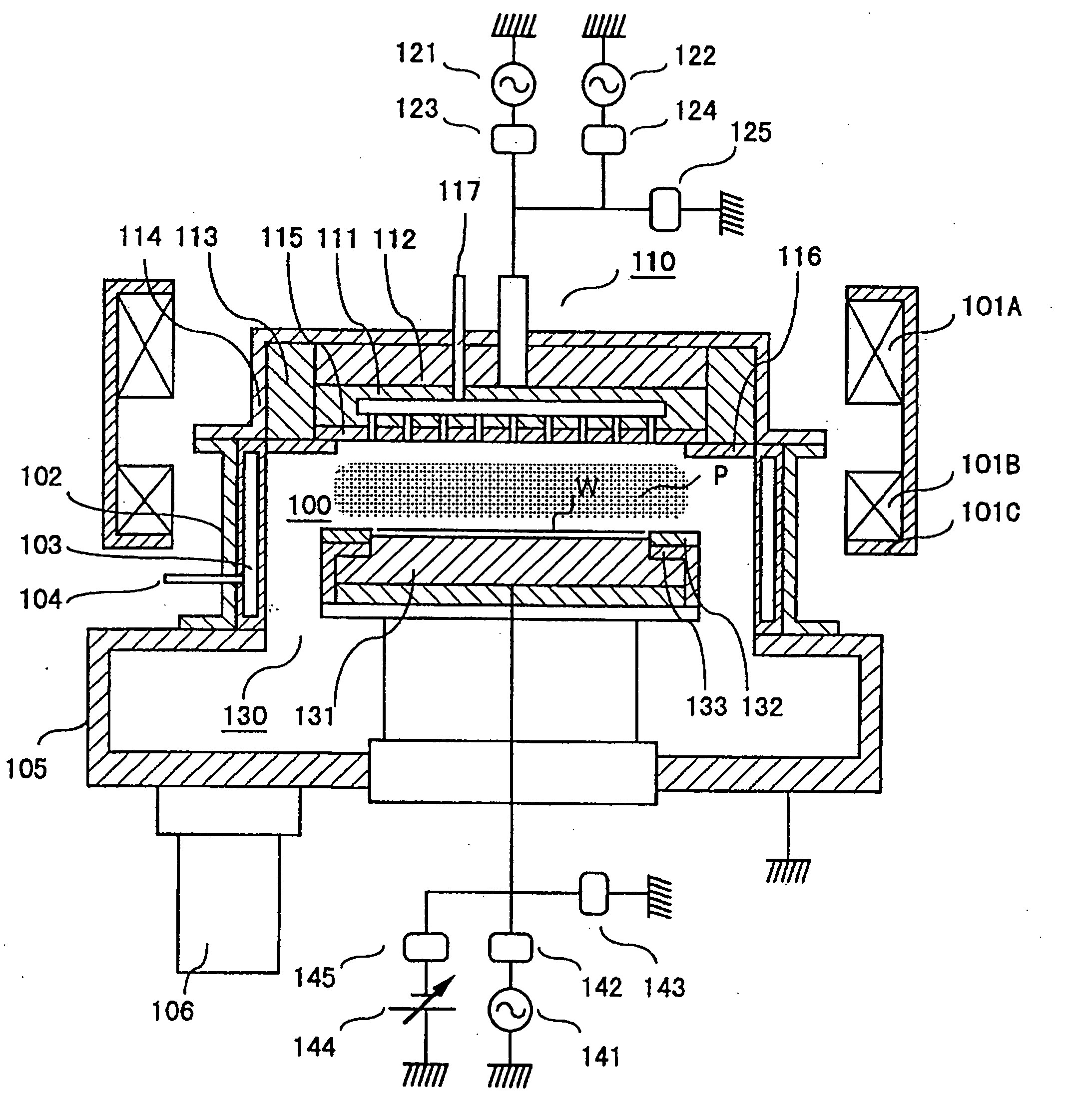
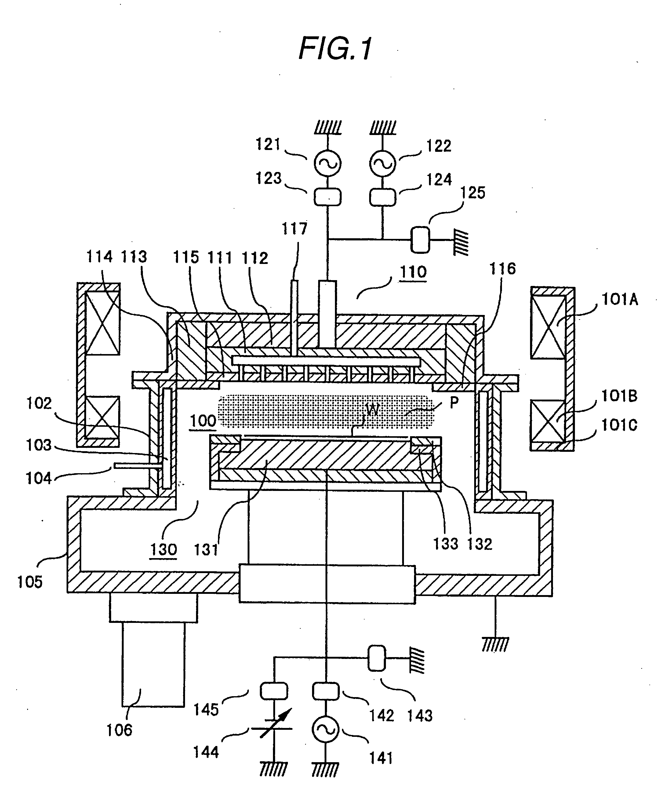
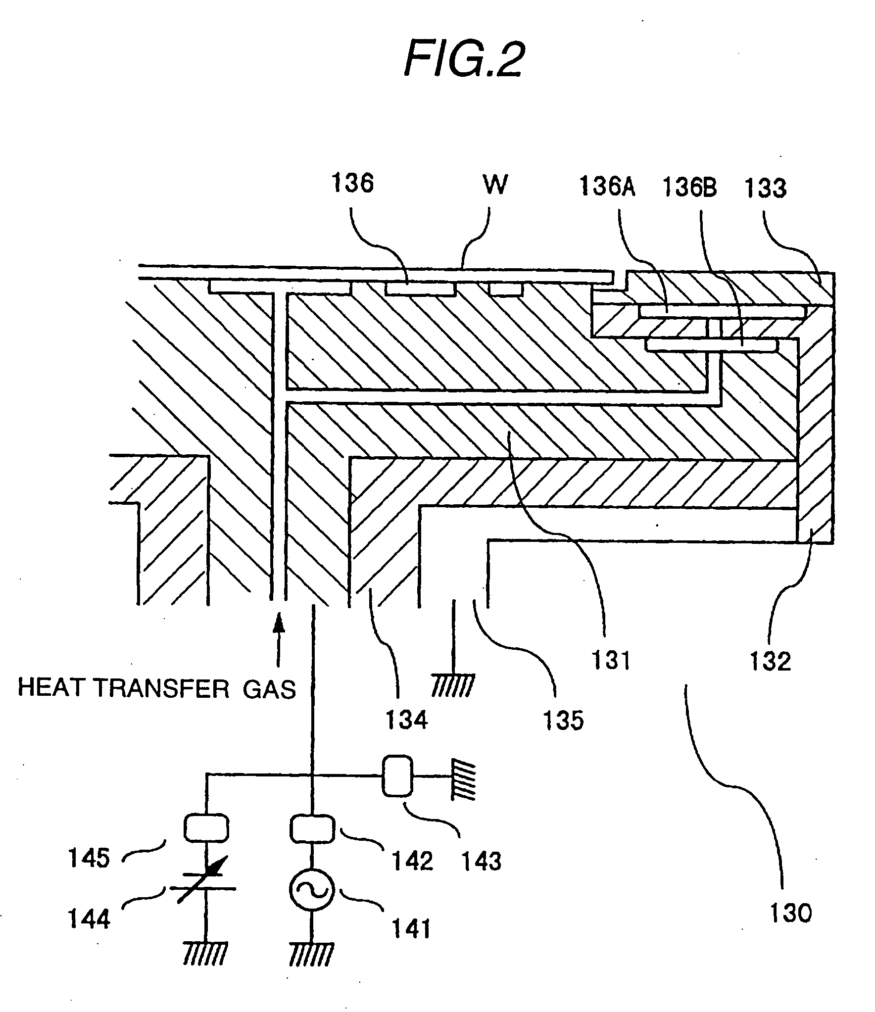
[0047]FIG. 1 shows an embodiment that the present invention is applied to a plasma etching apparatus of a magnetic field UHF band electromagnetic wave radiation and discharge system and is a cross sectional schematic diagram of the said plasma etching apparatus.

[0048] In FIG. 1, a processing chamber 100 is a vacuum vessel which can realize the degree of vacuum of about 10−6 Torr and the apparatus has an antenna 110 for radiating electromagnetic waves as a plasma generation means in an upper part of the processing chamber and a lower electrode 130 for loading a sample W such as a wafer in a lower part of the processing chamber. The antenna 110 and the lower electrode 130 are installed opposite to each other in parallel. A magnetic field forming means 101 comprising electromagnetic coils 101A and 101B and a yoke 101C is installed around the processing chamber 100 a...


PUM

PropertyMeasurementUnit
Distanceaaaaaaaaaa
Distanceaaaaaaaaaa
Temperatureaaaaaaaaaa

Abstract

A plasma processing apparatus includes a vacuum processing chamber, a plasma generating unit having a first power source, a gas supply unit, a lower electrode having a sample table surface for holding a sample in the vacuum processing chamber, and a vacuum pumping unit. The apparatus further includes a plate disposed at a position opposed to the sample table surface, a disc electricity conductor disposed in contact with the plate, a second power source for applying an RF frequency bias power to the disc electricity conductor, and a unit for controlling a temperature of the plate to a predetermined value. The plate is made of silicon or carbon at high purity, and the disc electricity conductor and the plate have a plurality of holes for introducing processing gas from the gas supply unit into the vacuum processing chamber.

Description

CROSS REFERENCE TO RELATED APPLICATION [0001] This application is a continuation application of Ser. No. 10 / 617,019, filed Jul. 11, 2003, which is a continuation application of Ser. No. 09 / 983,946, filed Oct. 26, 2001, which is a continuation application of Ser. No. 09 / 421,044, filed Oct. 20, 1999, which is a divisional application of Ser. No. 09 / 227,332, filed Jan. 8, 1999, now U.S. Pat. No. 6,171,438, which is a continuation-in-part application of Ser. No. 08 / 611,758, filed Mar. 8, 1996, now U.S. Pat. No. 5,874,012, entitled “Plasma Processing Apparatus and Plasma Processing Method”, by some of the inventors herein, the subject matter of the aforementioned applications being incorporated by reference herein.BACKGROUND OF THE INVENTION [0002] The present invention relates to a plasma etching apparatus and etching method and, more particularly, to a plasma etching apparatus and etching method suitable for forming a fine pattern in the semiconductor manufacture process. [0003] In the...

Claims


Application Information

Patent Timeline
IPC IPC(8): C23F1/00H01J37/32
CPCH01J37/32504H01J2237/022H01J37/32522
Inventor MASUDA, TOSHIOTAKAHASHI, KAZUESUEHIRO, MITSURUKAJI, TETSUNORIKANAI, SABURO
Owner MASUDA TOSHIO
Why Eureka
Try Eureka