Stage positioning unit for photo lithography tool and for the like

a technology of photo lithography and positioning unit, which is applied in the direction of photomechanical equipment, instruments, printing, etc., can solve the problems of high vibration sensitivity, high complexity of photolithography tools, and complex structure of stage units,

Inactive Publication Date: 2005-10-27
RIVIN EUGENY I
View PDF1 Cites 42 Cited by
  • Summary
  • Abstract
  • Description
  • Claims
  • Application Information

AI Technical Summary

Benefits of technology

[0012] It is an object of the present invention to provide for cancellation of dynamic forces generated in the process of acceleration / deceleration of the stage while not significantly complicating the design of the apparatus.
[0013] Another object of the present invention is to provide a high precision photo lithography apparatus and the like which simultaneously processes two objects (substrates) while having less complexity, being less costly to manufacture, and requiring less space than two apparatuses of conventional designs, each processing one object.

Problems solved by technology

The photolithography tools have extremely complex structures comprising the stage units, their driving motors, intricate and high precision illumination and focusing systems, and numerous precision sensing and measuring devices (usually, interferometers).
As a result, the structures have many joints and cannot be made very stiff, thus resulting in high sensitivity to vibrations, e.g. see E. I. Rivin, Passive Vibration Isolation, ASME Press, 2003.
To reduce damaging effects of the inevitable external vibrations on the precision semiconductor devices, extremely stringent and expensive to satisfy requirements to vibration levels of the floors and other supporting structures for the photolithography tools are mandated.
While the metrology frame is isolated from the intense dynamic forces, the complexity of the apparatus is increased by addition of massive and bulky force frame which has to be precisely aligned with the metrology frame.
Transmission of the intense reaction force to the floor excites floor vibrations which are undesirable not only for the tool to which the reaction frame belongs, even with vibration isolators, but also to other equipment units mounted on the floor.
Needless to say, such floors are extremely expensive.
Another shortcoming of this approach is the fact that the relatively long stroke movements of the massive stage unit cause shifts of the center of mass of the metrology frame and subsequent undesirable tilting of the metrology frame.
Compensation of the tilting in the system with the reaction frame requires a sophisticated and expensive servo-controlled system, e.g. as described in U.S. Pat. No. 5,844,666.
One disadvantage of this approach is its design complexity and, consequently, high costs.
This concept is also characterized by excessive design complexity.
However, since the two stages have different motion histories, the residual dynamic forces may still have harmful effects.
Also, the center of mass may shift in this system and the resulting tilting of the tool is not fully compensated.

Method used


Image

  • Stage positioning unit for photo lithography tool and for the like
  • Stage positioning unit for photo lithography tool and for the like
  • Stage positioning unit for photo lithography tool and for the like

Examples


Embodiment Construction

[0024] Preferred embodiments of the present invention are described with reference to the drawings.

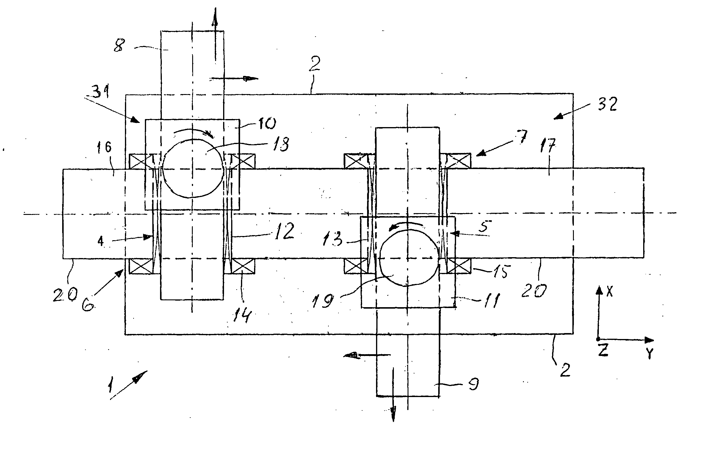
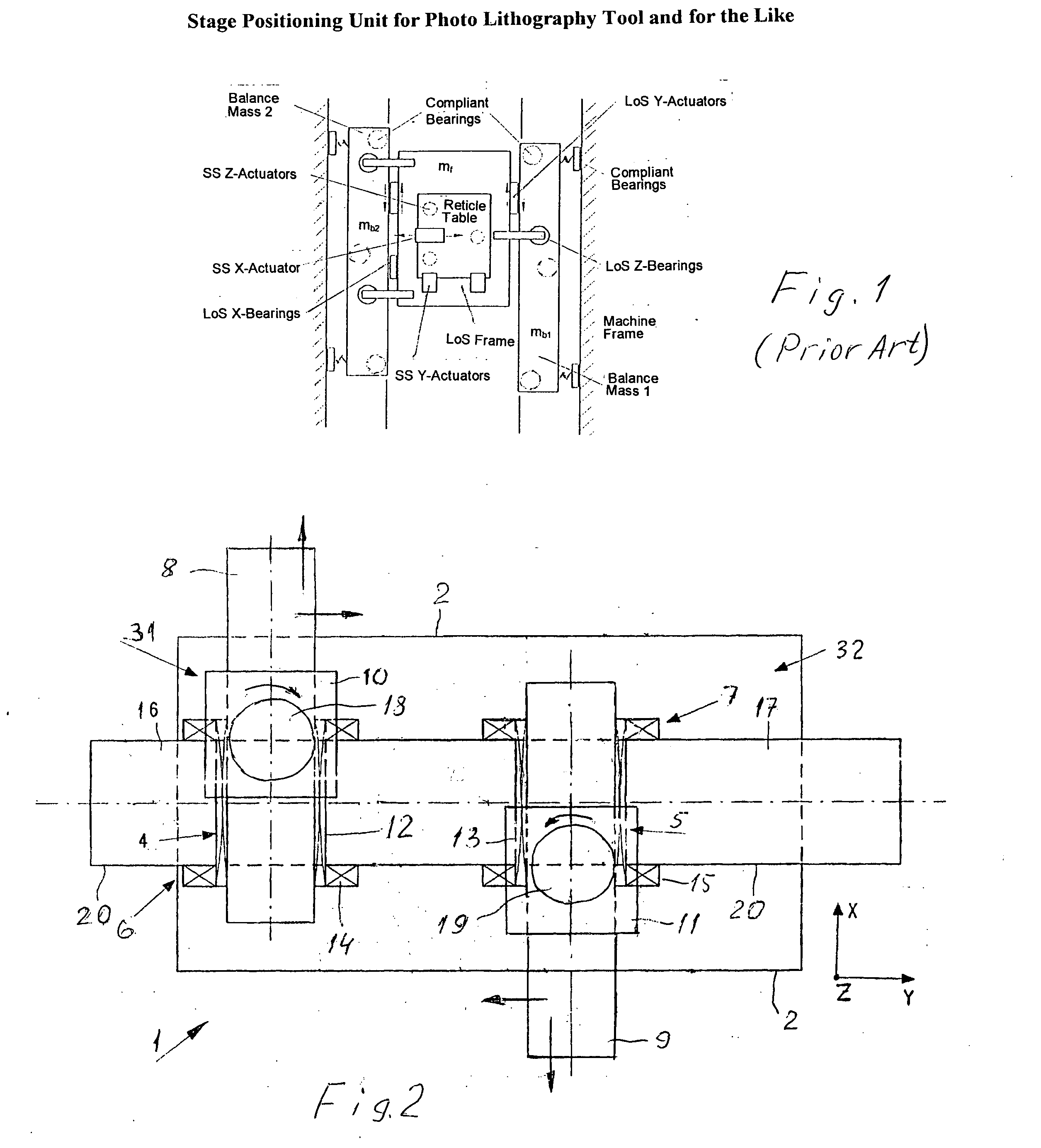
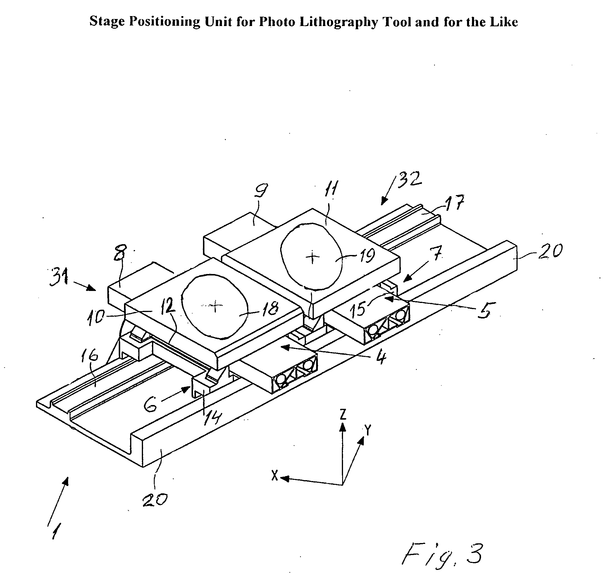
[0025]FIG. 2 is a diagrammatic top view of one embodiment of the substrate stage unit 1 of a photolithography tool according to the present invention. While the schematic depiction in FIG. 2 has distorted dimensional features, such as distances between the stages in X- and Y-directions, FIG. 3 gives an axonometric depiction which is less schematic and provides more realistic dimensional correlations within the substrate stage unit.

[0026] The stage unit 1 is mounted on base plate 2 and comprises two stage assemblies 31 and 32. Each stage assembly is provided with an X-actuator (linear motor) 4, 5, respectively, and with a Y-actuator 6, 7, respectively. Preferably, the Y-direction is the direction of the travel of the stage assemblies 31, 32 with the greatest magnitudes of accelerations of the pre-programmed motions. The X-actuators 4, 5 are each provided with a first (moving) part 8, ...


PUM

PropertyMeasurementUnit
sizesaaaaaaaaaa
accelerationsaaaaaaaaaa
timeaaaaaaaaaa

Abstract

A photolithography tool, e.g. for microelectronics production, having the stage units (both mask and substrate stage units) composed of two identical stage assemblies which are simultaneously driven with the programmed production motions. The acceleration time histories of the stage assemblies within the unit are identical but opposite in direction. Thus, the photolithography tool processes two substrates simultaneously while being free from objectionable dynamic loads and from shifts of its center of mass.

Description

[0001] Priority date for this Application is requested to be the filing date (Mar. 08, 2002) of the Provisional Patent Application 60 / 362,880 for “Photo Lithography Apparatus”. FIELD OF THE INVENTION [0002] The present invention relates to movable stage units for use with photo lithography and other semiconductor printing apparatuses, machine tools, microscopes or the like. In particular, it relates to movable stage units requiring high speed / high acceleration / high accuracy programmed motions in positioning vibration sensitive systems. BACKGROUND OF THE INVENTION [0003] A photolithography tool for printing semiconductor integrated circuits is a typical representative of high precision production equipment. On the one hand, positioning accuracies for the stages carrying the mask and the object (wafer) carrying multiple images of the printed circuits are measured in nanometers (nm), but on the other hand, the productivity requirements call for very high velocities and accelerations of...

Claims


Application Information

Patent Timeline
Patent Type & Authority Applications(United States)
IPC IPC(8): G03F7/20H02K1/00
CPCG03F7/70275G03F7/709G03F7/70766G03F7/70725
Inventor RIVIN, EUGENY I.
Owner RIVIN EUGENY I
Why Eureka
Try Eureka