Fault tolerant architecture for permanent magnet starter generator subsystem

a technology of starter generator and fault tolerance, which is applied in the direction of motor/generator/converter stopper, electric generator control, dynamo-electric converter control, etc., can solve the problems of increasing size and weight, dc brushed machine requires relatively frequent maintenance, and is difficult to meet the needs of maintenance and repair. , to achieve the effect of high reliability and fault toleran

Active Publication Date: 2005-10-27
ASTRONICS ADVANCED ELECTRONICS SYST
View PDF7 Cites 13 Cited by
  • Summary
  • Abstract
  • Description
  • Claims
  • Application Information

AI Technical Summary

Benefits of technology

[0005] The present invention relates to a starter / generator subsystem for small engine applications that utilizes a permanent magnet generator (PMG) and an electronic Power Conversion Unit (PCU). Further, the permanent magnet generator (PMG) does not require a field winding. The PMG and PCU architecture of this invention incorporates isolated subsystems and fault detection capabilities that lead to a highly reliable and fault tolerant system.
[0006] The fault tolerant architecture described herein enables safe operation even in the presence of various fault scenarios, and includes failsafe and fault monitoring features to ensure that appropriate actions can be taken to preclude potentially hazardous conditions. The advantages of the fault tolerant architecture and the associated PMG / PCU subsystem include lighter system weight, improved system reliability and higher performance capability.
[0007] The architecture achieves reduced weight for typical Electrical Power Generation and Distribution Systems (EPGDS), for several reasons. The PMG is significantly lighter, smaller and produces less nacelle drag than an equivalent performance brushed starter / generator (S / G). Also, while the PCU is larger and heavier than a GCU for a brushed S / G subsystem, the PCU advantageously incorporates a number of other functions of the EPGDS that are not included in typical GCUs, including ground fault detection, high current contactor functionality, bus current monitoring, fault monitoring and reporting functionality, and intelligent load sharing operation. Therefore, the total system weight typically favors the PCU based EPGDS. Further, the feeder cable between the PMG and PCU can be much lighter weight than the DC bus feeders (assuming the PMG / PCU architecture is designed appropriately). Additional reductions in EPGDS weight are typically applicable for the architecture since the PCU can be located remote from the engine so that DC bus cables are shorter and less complex.

Problems solved by technology

The DC brushed machine has a number of disadvantages in comparison to a permanent magnet machine of equivalent capacity, including increased size and weight, significantly lower reliability and higher maintenance.
The DC brushed machine requires relatively frequent maintenance, including replacement and servicing of brushes and bearings.
Since the output voltage and frequency of the PMG varies directly with driveshaft speed, a more complicated regulation and start excitation control method is required, as compared to that of a brushed starter / generator.
Also, the PMG output voltage cannot be controlled by means of adjusting stator field excitation (which is a common control technique used with brushed starter / generators), and therefore the PMG output cannot be electronically disabled in the event of a fault.
The inability to disable PMG output power during fault mode operation is of particular concern in high reliability applications such as aircraft.
A feeder cable short to engine or aircraft structure can result in a hazardous or unsafe condition for typical PMG / Power Conversion Unit (PCU) architectures.
However, the PMG is typically located on or near the engine system and must survive an extremely harsh environment, particularly in aircraft applications.
That harsh environment makes it very difficult (and often not technically feasible) to locate a contactor or circuit breaker close to the PMG.
Therefore, very few if any of the “fault tolerant” aspects are achieved.
The use of high power contactors to isolate these subsystems is necessary for practical non-isolated architectures since a single break-down in the feeder cable to aircraft structure can result in a catastrophic failure condition.
The PCU described in the U.S. Pat. No. 5,929,537 patent does not provide several reliability and / or performance features, including power factor corrected generator mode operation; ability to detect ground faults within the PMG, PCU and / or feeder cables; failsafe operation capability including operation in the presence of shorted windings in the PMG, shorted feeder wires, and / or failed PCU converters; or soft start and / or motoring start capability.

Method used


Image

  • Fault tolerant architecture for permanent magnet starter generator subsystem
  • Fault tolerant architecture for permanent magnet starter generator subsystem
  • Fault tolerant architecture for permanent magnet starter generator subsystem

Examples


Embodiment Construction

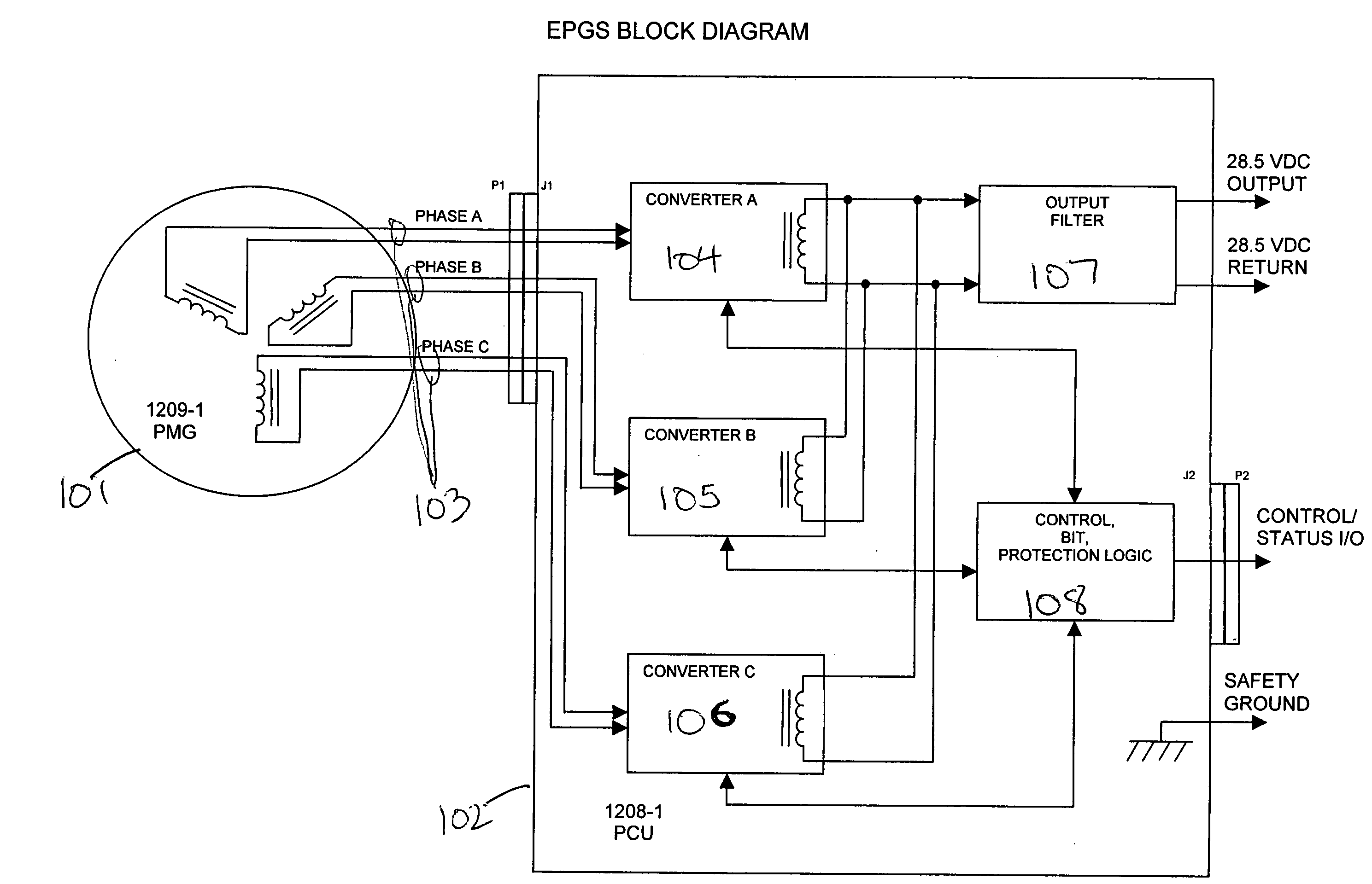
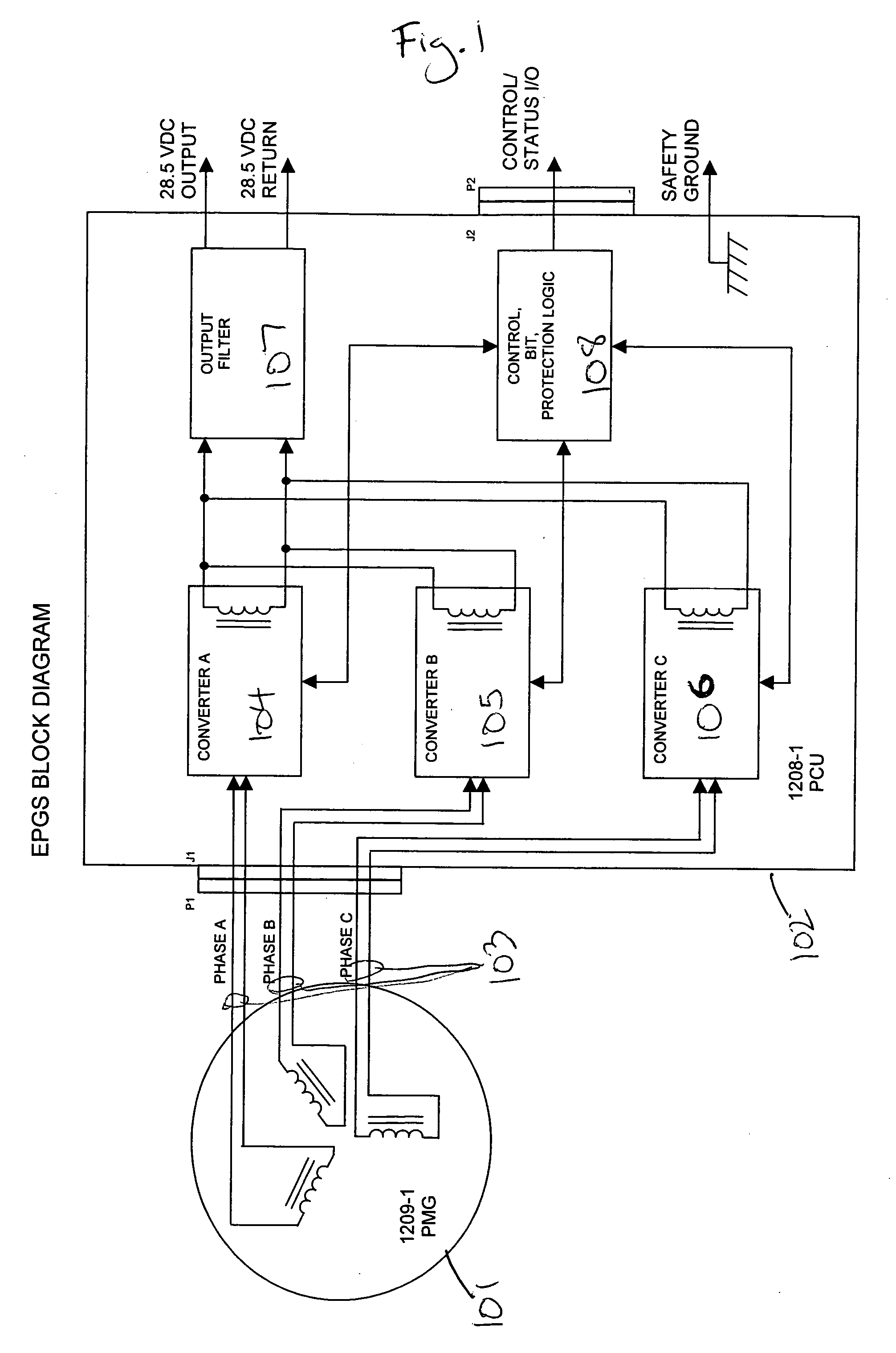
[0017]FIG. 1 is a block diagram of a power conversion unit (PCU) and permanent magnet generator (PMG) that illustrates the electrical interface. The PMG 101 is connected to the PCU 102 by a plurality of pairs of wires 103. Each pair of the wires carries a different phase of voltage between the PMG 101 and PCU 102. The voltage is derived in the PMG 101 and converted to the desired output voltage by the PCU 102 when the starter / generator subsystem is operating as a generator. The voltage is derived from a power source connected to the PCU 102 output (labeled “28.5VDC Output” and “28.5VDC Return” in FIG. 1), converted by the PCU 102 to an AC voltage of the desired form, and provided to the PMG 101, when the starter / generator subsystem is operating as a starter. The AC voltage derived in the PCU 102 while operating in the start mode, is specifically regulated in amplitude, frequency and phase angle so as to control the speed, direction of rotation and the torque produced by the PMG 101....


PUM


Abstract

A permanent magnet starter / generator subsystem configured in a fault tolerant architecture is described herein for small engine applications. The system allows for lighter system weight, improved system reliability, higher performance capability and reduced maintenance.

Description

BACKGROUND [0001] Starter / generator subsystems for small engine applications typically utilize DC brushed motor / generators and an electronic Generator Control Unit (GCU). The DC brushed machine has a number of disadvantages in comparison to a permanent magnet machine of equivalent capacity, including increased size and weight, significantly lower reliability and higher maintenance. The DC brushed machine requires relatively frequent maintenance, including replacement and servicing of brushes and bearings. Typically, maintenance intervals are 600 to 1000 operating hours for brushed machines in small aircraft applications. The brushed starter / generator also typically exhibits significant reductions in generator capability when operating at low speeds, and small aircraft applications often require operation over relatively wide speed ranges (typically 50% to 100% operational range in the generator mode). [0002] Currently, permanent magnet generators (PMGs) are sometimes used as starter...

Claims


Application Information

Patent Timeline
Patent Type & Authority Applications(United States)
IPC IPC(8): H02P3/00H02P9/02H02P9/06H02P9/14H02P9/30H02P15/00
CPCF02D2400/06F02N11/04H02P2101/30H02P9/305H02P29/022H02P9/02H02P29/032
Inventor PATTERSON, STANLEY C.
Owner ASTRONICS ADVANCED ELECTRONICS SYST
Why Eureka
Try Eureka