Intelligent probe card architecture

a probe card and intelligent technology, applied in the direction of measurement devices, semiconductor/solid-state device testing/measurement, instruments, etc., can solve the problems of increasing the complexity of the system, increasing the cost factor of the test system, and expensive replacement, so as to reduce the undesirable effects of fans, enhance the function of the test system controller, and reduce the life cycle of some test system controllers

Active Publication Date: 2005-10-27
FORMFACTOR INC
View PDF18 Cites 92 Cited by
  • Summary
  • Abstract
  • Description
  • Claims
  • Application Information

AI Technical Summary

Benefits of technology

[0016] In accordance with the present invention, a probe card is provided with a number of on board features enabling fan out of a test channel signal to multiple DUTs while limiting undesirable effects of fan out on test results. The on board probe card features further enable enhancing test system controller functions, effectively increasing the lifecycle of some test system controllers, providing more advanced functions without the cost of purchasing a more modern test system controller. The probe card in accordance with the present invention enables significant fan out with test integrity so that probe cards can be used with a limited channel test system controller to test a wafer with one touch down, a particularly desirable feature during burn in tests.
[0017] On board features of the probe card include one or more of the following: (a) DUT signal isolation provided by placing resistors in series with each DUT input to isolate failed DUTs, as described generally in U.S. Pat. No. 6,603,323 reference previously; (b) DUT power isolation provided by switches, current limiters, or regulators in series with each DUT power pin to isolate the power supply from failed DUTs, allowing a single test system controller power supply to power multiple DUTs; (c) self test provided using an on board micro-controller or FPGA and associated multiplexers and D / A converters, on board self testing being necessary with fanned out test system controller resources since test system controller integrity checks may no longer be valid; (d) stacked or vertically oriented daughter cards provided between test system controller connections which form an outline area on the PCB of the probe card, the stacked daughter cards to accommodate additional circuitry used in accordance with the present invention, and to provide the additional circuitry in close proximity to the PCB, space transformer and other components originally forming the probe card; and (e) use of a communications bus between a controller provided on the base PCB and separate daughter cards and the test system controller to minimize the number of interface wires between the base PCB and the daughter cards or between the base PCB and the test system controller. The bus can further be configured to distribute analog signals to the DUTs through the use of serial to parallel D / A or A / D converters on the probe card, providing for minimum wiring and minimum use of PCB area.

Problems solved by technology

However, a test system controller with increased test channels is a significant cost factor for a test system, as is a probe card with complex routing lines used to accommodate multiple parallel test channels.
Further, less touch downs to the wafer decrease the likelihood of damaging the wafer, and less touch downs limit wear on the probes in the test system, which may be expensive to replace.
Fan out of the test signals in a probe card between a test system controller and DUTs, however, not only increases the complexity of a system, but also can cause inaccurate test results.
With a test system having probe card fan out, a fault (short circuit) in a component connected on a fanned out line will severely attenuate the test signal for all devices on the fanned out test system channels.
Probe cards, serving as an interface between a test system controller and a wafer, are typically much less expensive than a test system controller, and typically replaced after a much shorter lifecycle than the test system controller due to wear of probes on the probe card.

Method used


Image

  • Intelligent probe card architecture
  • Intelligent probe card architecture
  • Intelligent probe card architecture

Examples


Embodiment Construction

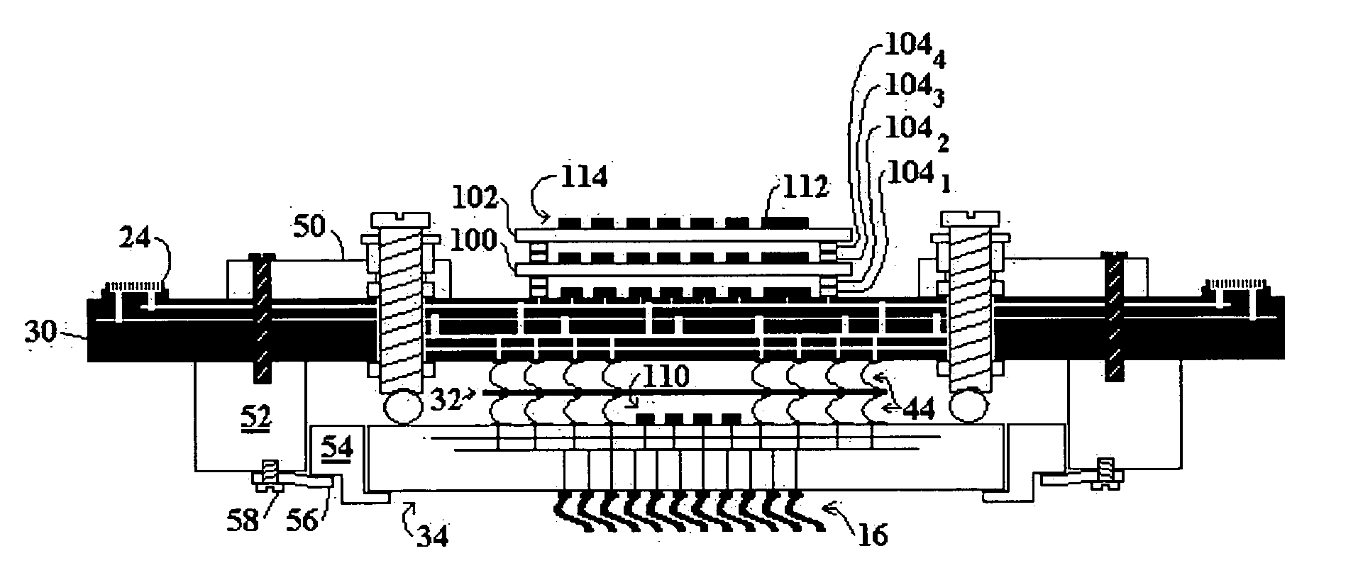
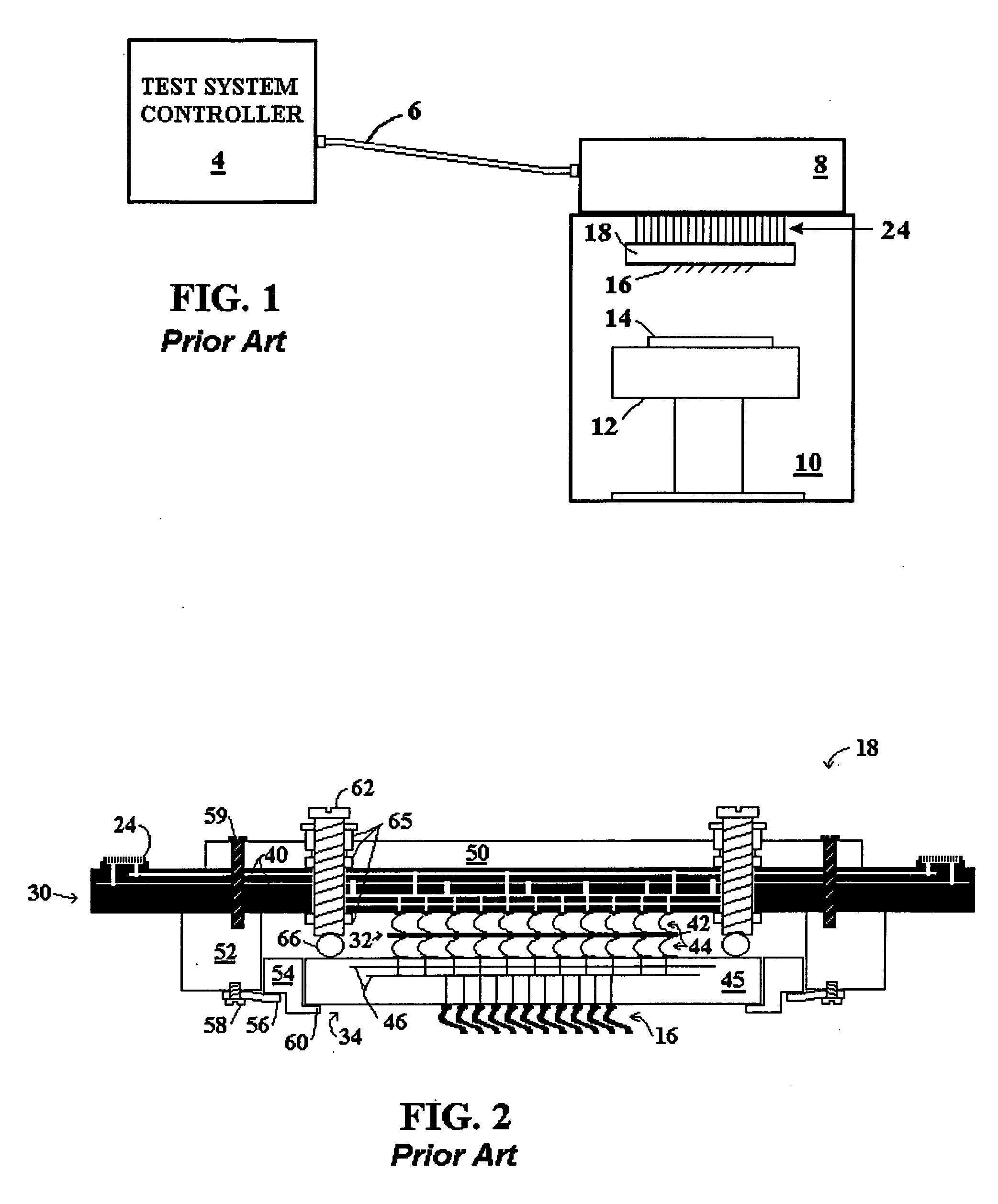
[0026]FIG. 5 shows a cross sectional view of a probe card, modified from the probe card configuration shown in FIG. 2 to include on board components, in accordance with the present invention, including daughter cards 100 and 102. For convenience, components carried over from FIG. 2 to FIG. 5 are similarly labeled. The daughter cards are shown in FIG. 5 as connected by stacked connectors 1041-4. The stacked connectors are attached to opposing card surfaces, and include male and female mating connectors. For example connector 1041 is connected to the base PCB 30, while connector 1042 is connected to daughter card 100. The stacked connectors can be ZIF, pogo pin, or other type connectors suitable for interconnecting printed circuit boards. The connectors make the daughter cards removable so that different daughter cards can be easily installed, depending on the test environment. Although shown with removable connectors, in one embodiment, the daughter cards can be rigidly connected, su...


PUM


Abstract

A probe card for a wafer test system is provided with a number of on board features enabling fan out of a test system controller channel to test multiple DUTs on a wafer, while limiting undesirable effects of fan out on test results. On board features of the probe card include one or more of the following: (a) DUT signal isolation provided by placing resistors in series with each DUT input to isolate failed DUTs; (b) DUT power isolation provided by switches, current limiters, or regulators in series with each DUT power pin to isolate the power supply from failed DUTs; (c) self test provided using an on board micro-controller or FPGA; (d) stacked daughter cards provided as part of the probe card to accommodate the additional on board test circuitry; and (e) use of a interface bus between a base PCB and daughter cards of the probe card, or the test system controller to minimize the number of interface wires between the base PCB and daughter cards or between the base PCB and the test system controller.

Description

BACKGROUND [0001] 1. Technical Field [0002] The present invention relates to a probe card configuration for a test system used to test integrated circuits (ICs) on a wafer. More particularly, the present invention relates to a probe card configuration with intelligent on board features that can, for example, enable the probe card to distribute a single channel from a test system controller to multiple test probes to connect to the ICs on a wafer. [0003] 2. Related Art [0004] When testing ICs on a wafer, it is cost effective to test as many devices as possible in parallel, thus reducing the test time per wafer. Test system controllers have evolved to increase the number of channels and hence the number of devices that can be tested in parallel. However, a test system controller with increased test channels is a significant cost factor for a test system, as is a probe card with complex routing lines used to accommodate multiple parallel test channels. It is, thus, desirable to provide...

Claims


Application Information

Patent Timeline
Patent Type & Authority Applications(United States)
IPC IPC(8): G01R1/073G01R1/36G01R31/02G01R31/28G01R31/319G01R35/00
CPCG01R1/07385G01R1/36G01R35/00G01R31/31905G01R31/2889H01L22/00
Inventor MILLER, CHARLES A.CHRAFT, MATTHEW E.HENSON, ROY J.
Owner FORMFACTOR INC
Why Eureka
Try Eureka