Over-lock for self-storage units

a self-storage unit and over-lock technology, applied in the field of electronic security systems, can solve the problems of aggravating the delay between payment time-consuming and costly application and removal of over-locks, and the customer cannot gain access to the unit immediately after making the payment, so as to reduce labor requirements

Inactive Publication Date: 2005-10-27
PREFERRED TECH SYST
View PDF13 Cites 20 Cited by
  • Summary
  • Abstract
  • Description
  • Claims
  • Application Information

AI Technical Summary

Benefits of technology

[0012] A major advantage of the present invention is that the electronically activated over-lock system will reduce the labor requirements for managing a self-storage facility. This advantage derives from the fact that the over-locks can be switched between activated and deactivated conditions without going to each storage unit and manually performing the over-lock process. The system will automatically lock or unlock the over-locked based on the status of the unit and the status of the customer.
[0013] Another major advantage of the present invention is that the self-storage system is able to rent storage units to new tenants and to accept payments from delinquent tenants, and then provide access to storage units at the same time. The electronically activated over-lock will automatically lock or unlock the over-locks based on the status of the unit and the status of the customer without onsite personal.
[0014] These and other features and their advantages will be apparent to those skilled in the art from a careful reading of the Detailed Description of Preferred Embodiments, accompanied by the following drawings.

Problems solved by technology

Applying and removing over-locks is time-consuming and costly because it includes the manager's time to over-lock the unit and unlock the unit along with the costs associated with the over-locks themselves.
If the manager has over-locked the self-storage unit, then the customer cannot gain access to their unit immediately after making the payment.
The delay between payment and removal of the over-lock is aggravating to tenants who may then demand immediate attention.
This creates a similar problem for the self-storage owner.
Moreover, if a self-storage owner wants to rent a self-storage unit via a remote process, the customer does not have access to the self-storage unit until the vacant unit over-lock has been removed.
However, in view of the above, there still remains a need for an electronically-controlled self-storage system that provides facility managers and owners with capabilities that are not possible with the conventional methods.

Method used


Image

  • Over-lock for self-storage units
  • Over-lock for self-storage units
  • Over-lock for self-storage units

Examples


Embodiment Construction

[0020] The present invention is an over-lock security system. Although the system will be described with respect to its application in self-storage facilities, it is clear that the system could be used anywhere an over-lock system is useful.

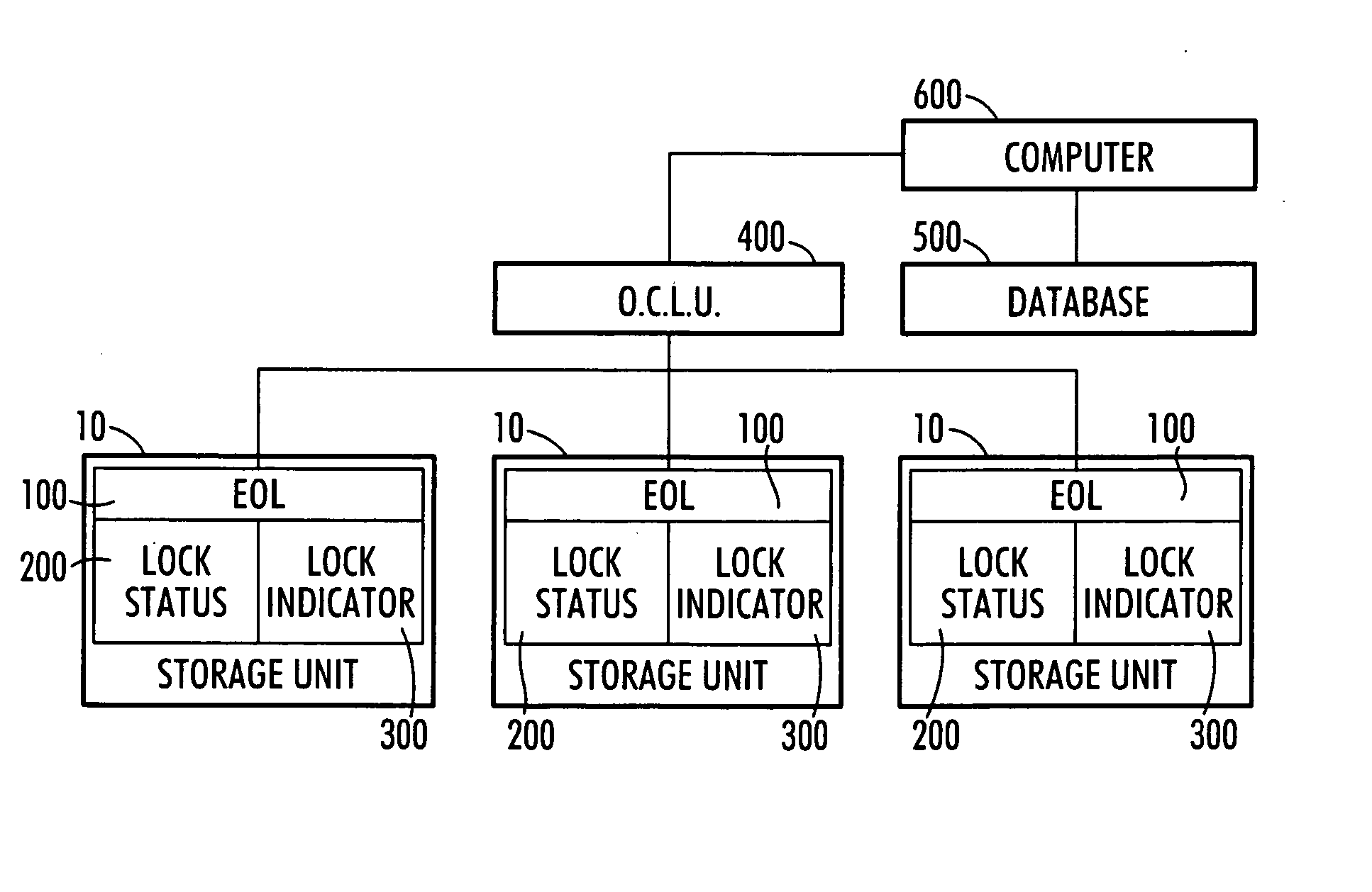
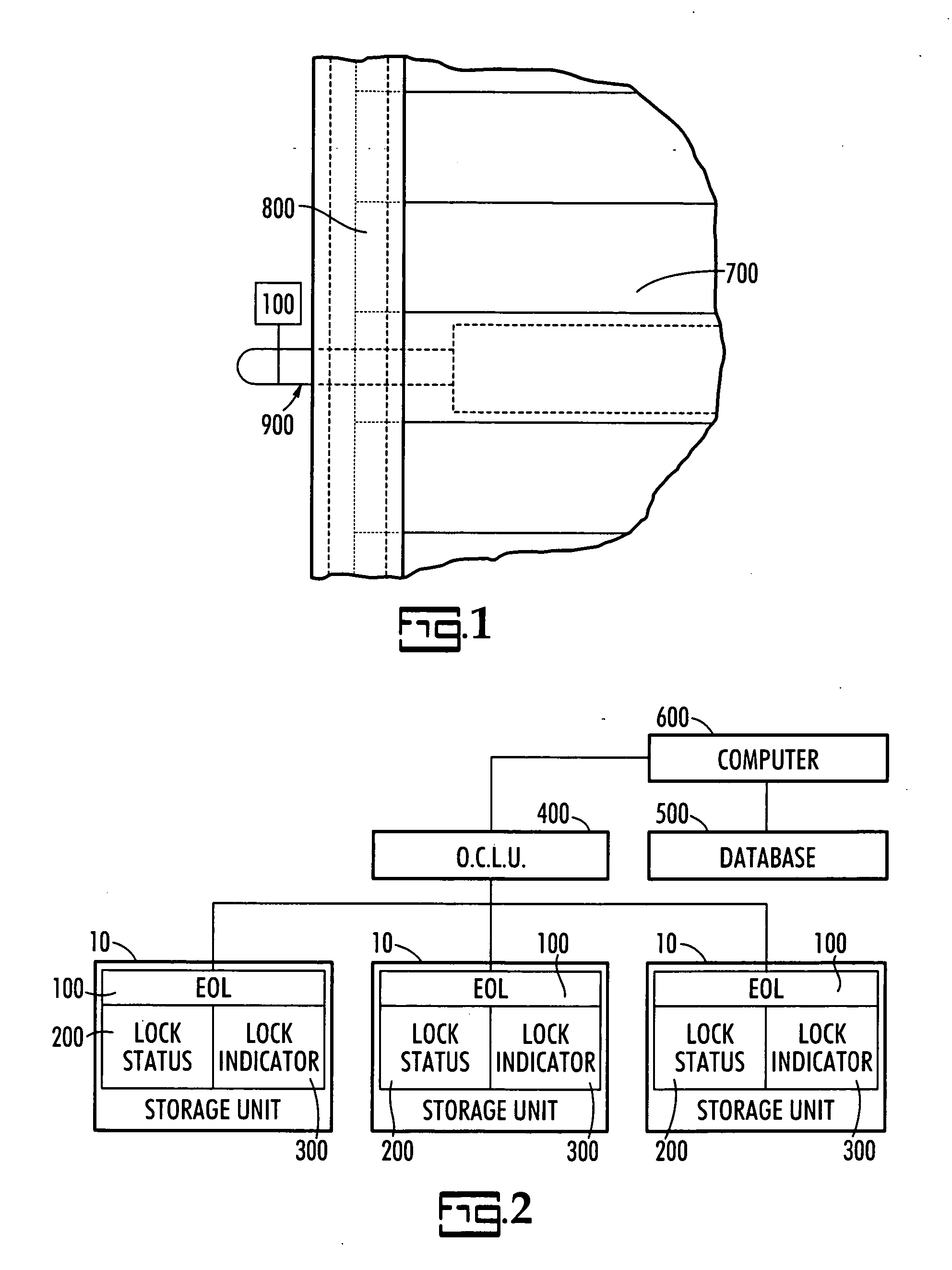
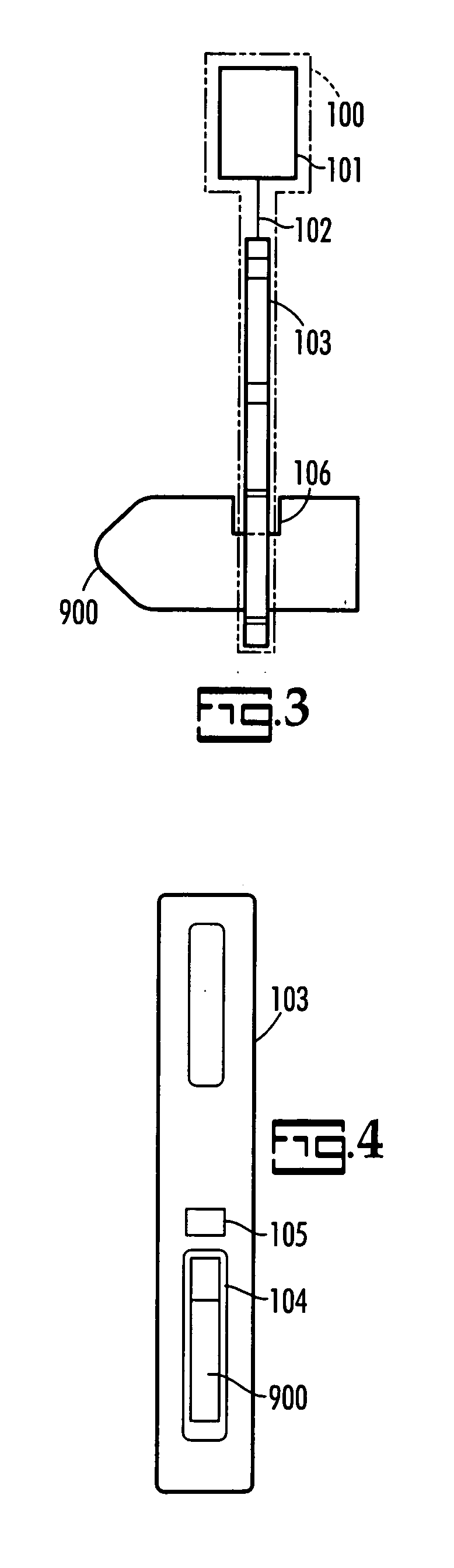
[0021] Referring to FIGS. 1 and 2, each self-storage unit 10 is equipped with an over-lock 100 that is preferably mounted on the inside of self-storage unit 10, as seen best in FIG. 2, but, using a wireless connection, over-lock 100 may be mounted on the outside of unit door 700. Each over-lock 100 can have optional equipment including a lock status indicator 200 and an over-lock indicator 300. Each over-lock 100 can be switched remotely and wirelessly via an over-lock control unit 400 between opened (unlocked) or closed (locked) positions, based on the current status of the unit and customer, which status is available to a controller 600 having access to a computer database 500. Communication between the over-lock 100 and the over-lock control ...


PUM


Abstract

The present invention is an electronically controlled self-storage over-lock system that uses distributed processing to allow management to automatically over-lock tenants' units when their accounts become delinquent or when storage units are not rented. Once the self-storage unit door is locked by the over-lock system, tenants cannot access their units their accounts are brought current. Preferably, the over-lock, when in the locked position, prevents movement of the self-storage unit door hasp.

Description

CROSS REFERENCE TO RELATED PATENTS [0001] The priority benefit of U.S. provisional patent application Ser. No. 60 / 564,839, filed Apr. 23, 2004, is claimed.BACKGROUND OF THE INVENTION [0002] The present invention relates generally to electronic security systems and to electronic over-lock systems for self-storage units in particular. [0003] In the U.S., a burglary currently occurs every 13 seconds. Accordingly, security systems have gained popularity for homeowners and businesses alike. For businesses that lease spaces, a security system is a necessity to compete in the marketplace. Whether it is the lease of apartments, office space, industrial space or self-storage facilities, the ability to attract new customers is greatly dependent upon a reliable security system to protect the tenants' valuable assets. [0004] For self-storage facilities a reliable security system is important, not only to attract new tenants, but also to retain existing tenants. The term self-storage facility de...

Claims


Application Information

Patent Timeline
Patent Type & Authority Applications(United States)
IPC IPC(8): E05B41/00E05B47/00E05B47/06E05B63/14E05B65/48G06F7/04
CPCE05B41/00E05B47/06E05B2047/0094E05B65/48E05B2047/0069E05B63/143
Inventor LOFTIN, JONTOY, ROBERT
Owner PREFERRED TECH SYST
Why Eureka
Try Eureka