
Color liquid crystal display device

Inactive Publication Date: 2005-10-27
CANON KK
View PDF9 Cites 18 Cited by
  • Summary
  • Abstract
  • Description
  • Claims
  • Application Information

AI Technical Summary

Benefits of technology

[0039] The present invention is particularly intended to improve the above-described conventional examples, and is to reduce power consumption of light sources while inhibiting the color sequential artifact at the time of performing display by four fields of R, G, B and W.
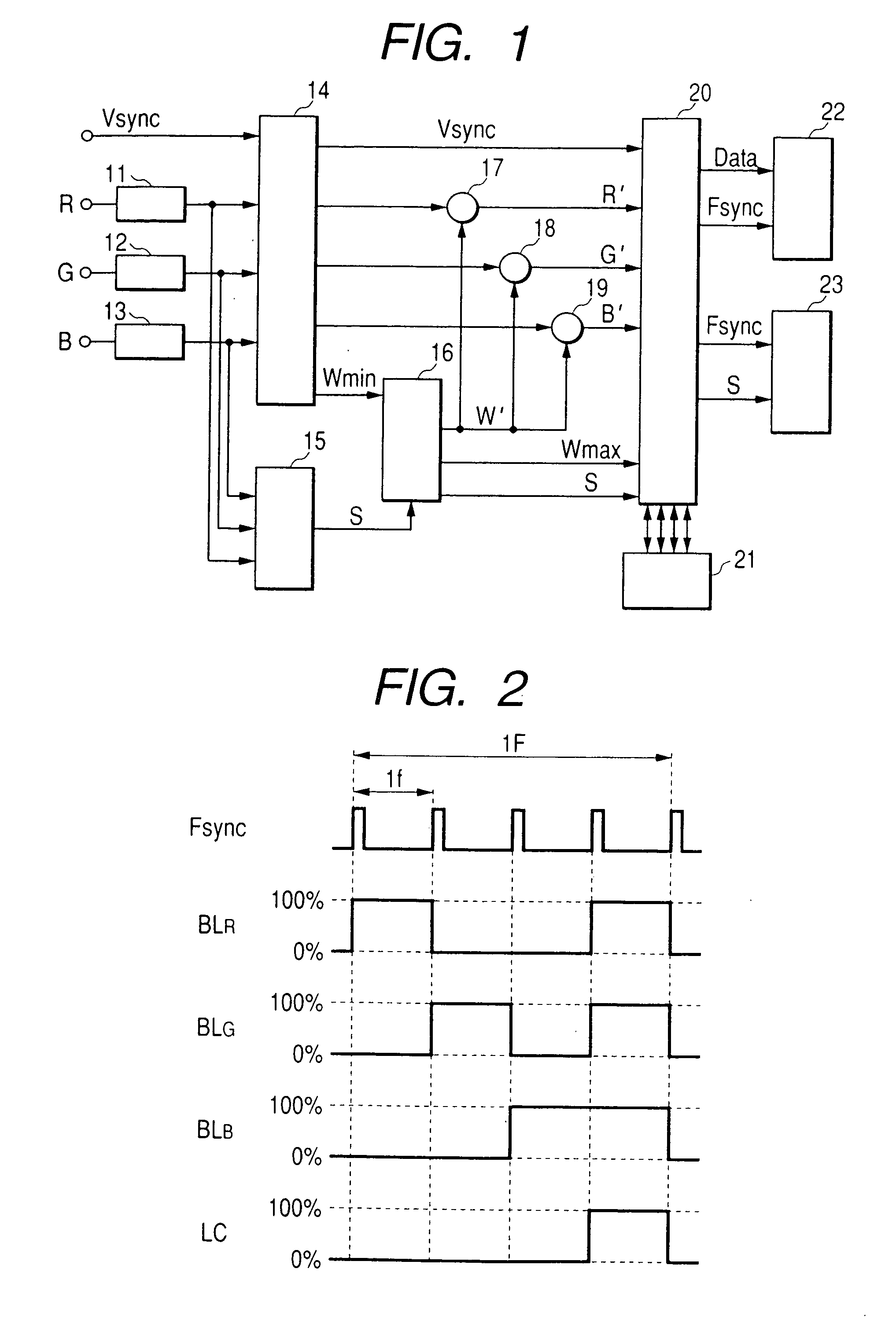
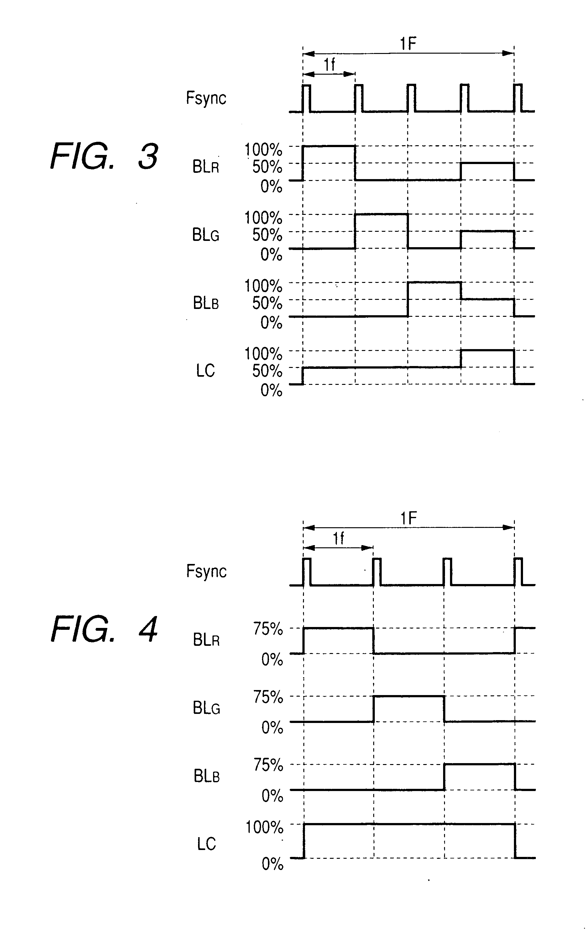
[0043] Therefore, as compared with the conventional example 2, each of R, G and B light sources is lit at the maximum intensity in the W field, for example in the case of dark images, by reducing the emission intensity in the W field, power consumption of light sources in the W field can be reduced, and thus power consumption of the device can be reduced.
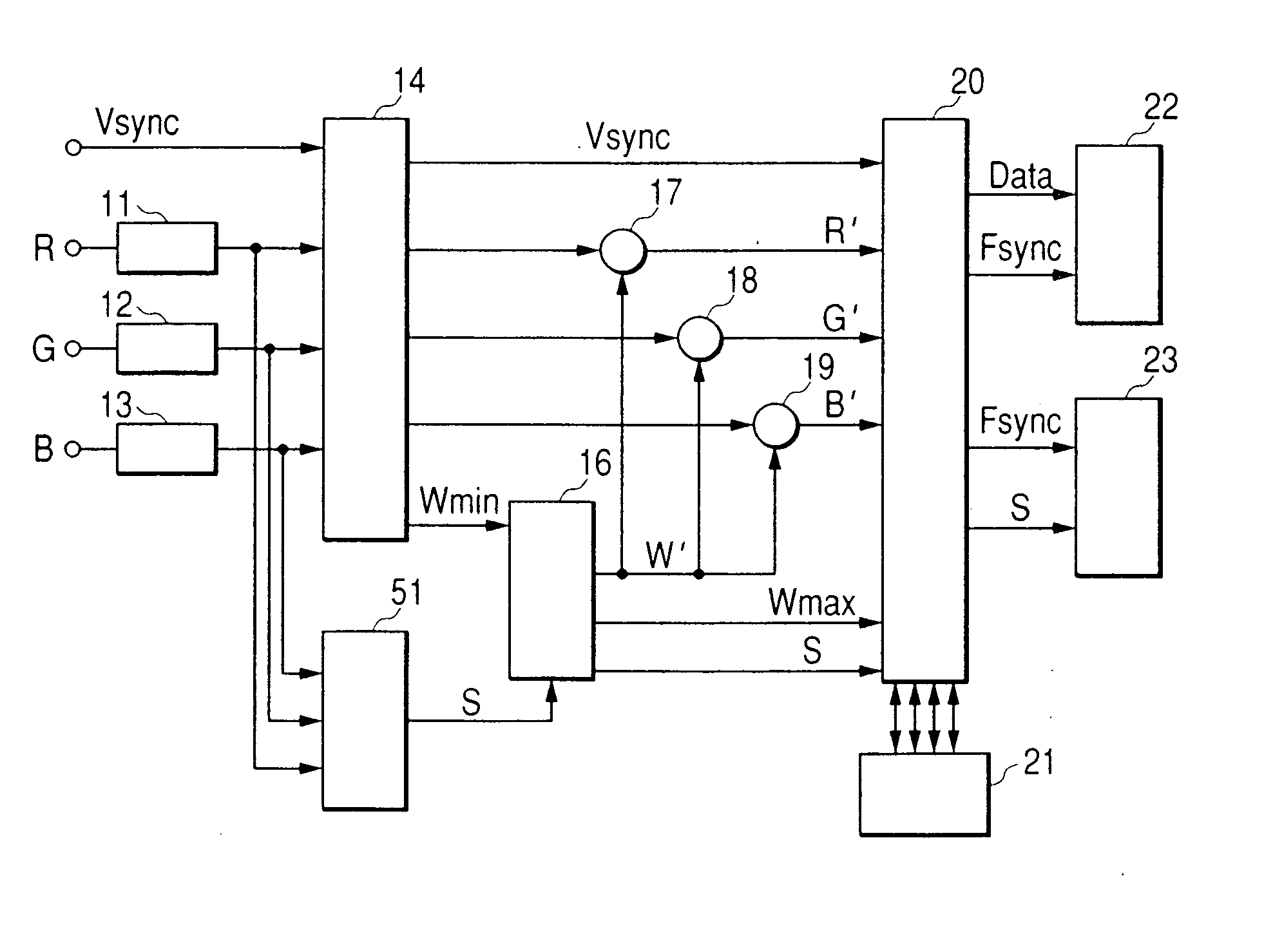
[0045] 3) The proportion S of the brightness level of the white signal to be displayed in the W field is set for the maximum brightness Wmax in one frame unit of the above-described Wmin signal, and the brightness level having a magnitude of Wmax multiplied by this proportion S is defined as a maximum display brightness in the W field. In accordance therewith, the emission intensity of the light source for emitting light is decreased to further reduce power consumption. This proportion S can be automatically set corresponding to the image, or can be freely set by the observer using a switch or the like.
[0049] 5) In addition, when the above-described proportion S equals zero percent (0%), display is not performed in the W field, and thus the W field itself is eliminated to drive light sources only in the three fields of R, G and B, thereby further reducing power consumption.

Problems solved by technology

Furthermore, in FIG. 15, a state of transient transmission due to delay of speed of response by the liquid display part and delay at the time of on / off of the light sources of three primary colors is not considered.
However, for example, if horizontal and vertical scan frequencies by two times compared to the conventional frequencies (the field frequency is increased to a sixfold-speed), for example, power consumption is increased due to enhancement of the speed of data transfer, the speed of response by the liquid crystal is reduced to provide only poor display, and so on, thus rising other problems.
However, the method of the conventional example 2 including the W field has an increased power consumption of the light source and an inferior efficiency of light usage, in comparison with the display method of the conventional example 1.

Method used


Image

  • Color liquid crystal display device
  • Color liquid crystal display device
  • Color liquid crystal display device

Examples


Embodiment Construction

[0066] A liquid crystal display device of the present invention will be described in detail below by using the drawings.

[0067] The liquid crystal display device comprises a liquid crystal display part, light sources having three primary colors and generating on a white color by mixture thereof, namely R, G and B light sources, specified means for converting an inputted color image signal into a signal for driving a liquid crystal panel, and means for controlling the brightness of the light sources. The liquid crystal display part for use in the present invention is a monochrome display panel having no color filters, and may be any liquid crystal element of high speed response such as a conventional twisted nematic liquid crystal element and a ferroelectric liquid crystal. Also, it is not limited to the liquid crystal element, and may be a light-receiving type and projection type display element.

[0068] A block diagram of a preferred embodiment of the liquid crystal display device o...


PUM


Abstract

A color liquid crystal display device includes at least a liquid crystal display part, and light sources for irradiating the liquid crystal display part with lights of three primary colors, respectively, and performs display of one frame by respective fields of three primary colors and a white field displayed with a mixture of the three primary colors in the liquid crystal display part. The device further includes a circuit for comparing brightness levels of inputted three primary color signals for one frame with each other to define a maximum value thereof as a brightness level of a white signal for one frame; a circuit for setting a proportion of the brightness level of the white signal to be displayed in the white field; and a light source driving part for driving the light sources of the three primary colors so that the white field emits light depending on the brightness level of the white signal and the proportion.

Description

BACKGROUND OF THE INVENTION [0001] 1. Field of the Invention [0002] The present invention relates to a liquid crystal display device for performing color display that is used in a color television, a personal computer or the like, and to particularly a liquid crystal display device for providing three primary color display by time-sharing, and providing full color display by mixing the three primary colors without using any color filter. [0003] 2. Related Background Art [0004] In recent years, liquid crystal displays of color display have been grown in demand due to advancement of personal computers. [0005] In liquid crystal display devices that are currently on the market, color filters for three primary colors of red (R), green (G) and blue (B) are placed in positions corresponding to pixels, backlights are placed on the back face, and white light is applied to obtain color images. [0006] On the other hand, a color liquid crystal panel of field sequential mode that has a liquid cr...

Claims


Application Information

Patent Timeline
IPC IPC(8): G02F1/133G09G3/20G09G3/34G09G3/36H04N9/30
CPCG09G3/3413G09G3/3611G09G2310/0235G09G2320/0242G09G2360/16G09G2320/0276G09G2320/103G09G2330/021G09G2340/06G09G2320/0261
Inventor YOSHINAGA, HIDEKIMORI, HIDEOMIURA, SEISHI
Owner CANON KK
Learn More