
Large field of view 2X magnification projection optical system for FPD manufacture

Inactive Publication Date: 2005-10-27
ASML HLDG NV
View PDF54 Cites 18 Cited by
  • Summary
  • Abstract
  • Description
  • Claims
  • Application Information

AI Technical Summary

Benefits of technology

[0022] The designs for the 1.5× and larger magnification optical systems all typically have at least three powered mirrors. A corrector, positioned either near the reticle or near the substrate, can be added to the three mirror design to improve the systems optical performance. The corrector can be a reflective, or a refractive design. The corrector can have an aspheric surface, and optionally a powered surface. The corrector can be a flat glass plate, or a lens having concave-convex, concave-concave or convex-convex surfaces.

Problems solved by technology

This places severe requirements on the optics used in the projection optical system.
Specifically, many existing optical designs, if scaled up to 42 inch FPD manufacturing size, become unreasonably large.
While fabricating mirrors of this size is possible, they may not be cost effective in a FPD lithography tool.
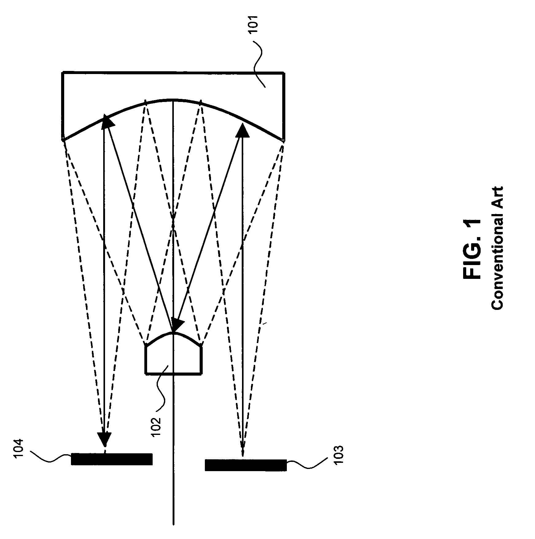
The mask making infrastructure to manufacture 1× reticles to work with the system in FIG. 1 for 42 to 60 inch FPDs is very limited.
Adding the capacity to manufacture masks in the quantities needed will be very expensive and time consuming to develop.
Adding the mask infrastructure development cost to the FPD may result in a FPD product cost that is unacceptably high.
This is a very time consuming process to create the full FPD.
Printing FPDs using a stitching based imaging process results in low yields, and therefore high costs, during the manufacturing process.
This is due to the fact that the type of imaging errors that occur during the stitching process are easily discernible when viewing large FPDs with a naked eye.
As the FPD size increases the stitching related errors also increase resulting in ever more complicated FPD exposure tools.
It is generally thought that a cost effective stitching imaging technique for fabricating 42-inch FPDs will not work.
This size reticle can only be produced in very limited volumes making it impractical to use where large quantities of 42 inch display need to be manufactured.
These sizes are beyond the current capability of reticle manufacturers.

Method used


Image

  • Large field of view 2X magnification projection optical system for FPD manufacture
  • Large field of view 2X magnification projection optical system for FPD manufacture
  • Large field of view 2X magnification projection optical system for FPD manufacture

Examples


example 1

[0095] A four mirror ringfield optical design form with a refractive corrector plate is proposed, shown in FIG. 3, for printing Generation 6 FPDs and beyond that operates at magnifications consistent with mask substrate sizes from Generation 5 (32 inches) and Generation 4 (about 22 inches). In particular, a nominally 2× optical design would enable FPD manufacture up to about 60 inches in size to be produced using a 32-inch Generation 5 mask substrate. An example of the 2× optical system is a 42-inch Generation 6 FPD being printed using a 21-inch diagonal mask pattern that is written on a 32-inch diagonal mask substrate. Table 1 shows the sizes of the Generation 6, 7 and 8 mask patterns with a 2× system relative to the size of a Generation 5 substrate.

TABLE 1Mask Pattern Sizes For Generation 6, 7 and 8 FPDs With 2XProjection OpticsFPDGenerationMask Size For 2XDiag-Actual Screen SizeProjection OpticsNum-onalHorizontalVerticalHorizontalVerticalber(in)(in)(in)(in)(in)Comments53227.815...

example 2

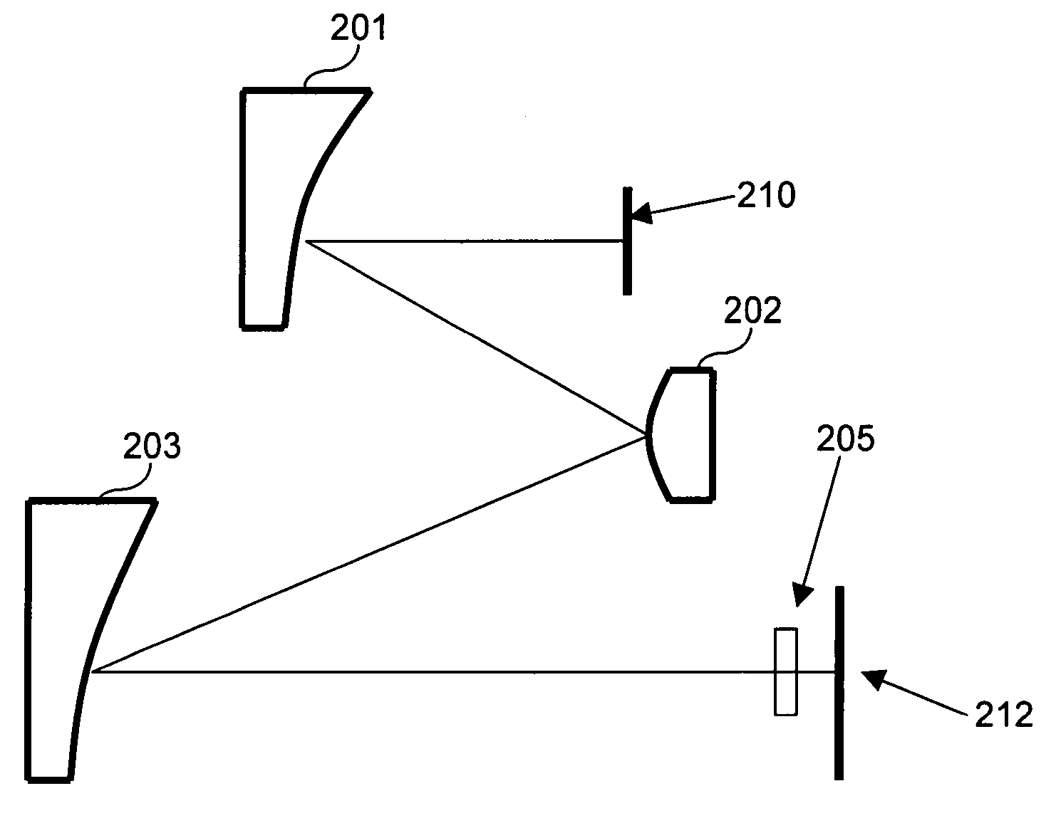
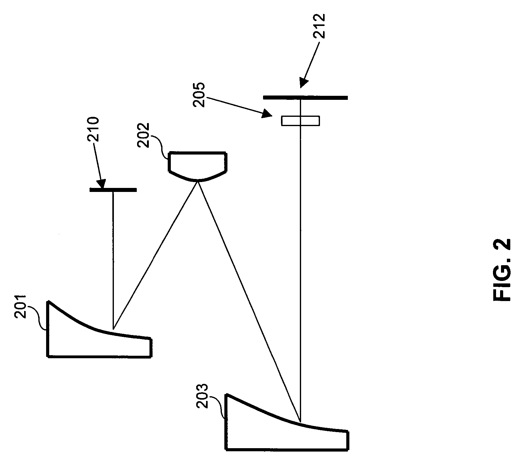
[0103] A three-mirror exemplary ringfield optical design form with a refractive corrector plate, shown in FIG. 2, can be used for printing Generation 6 FPDs and beyond, that operates at magnifications consistent with mask substrate sizes for Generation 5 and 4. In particular, a nominally 2× optical design with mirrors 201-203 enables FPDs up to about 60-inches in size to be produced using a 32-inch Generation 5 mask substrate.

[0104] The 2× optical design form of FIG. 2 utilizes three powered mirrors 201, 202, 203, which are all off-axis aspheres in the baseline design. A corrector plate 204, which is located near the image plane, has two flat surfaces (radii of curvature equal to infinity), but one surface has an aspheric curve that is designed to correct distortion. The thickness of the corrector plate 204 is chosen based upon the amount of astigmatism to be corrected. The exact radii of curvatures, aspheric coefficients and spacings for the mirrors 201, 202, 203 depend on the sli...

example 3

[0109] An exemplary four-mirror ringfield optical design form, shown in FIG. 7, is proposed for Generation 6 and beyond that operates at magnifications consistent with mask substrate sizes from Generation 5 and 4. In particular, a nominally 2× optical design would enable FPDs up to about 60-inches in size to be produced using a 32-inch Generation 5 mask substrate.

[0110] The 2× optical design form of FIG. 7 utilizes four powered mirrors 701-704, three of which are off-axis aspheres in the baseline design. The exact radii of curvatures, aspheric coefficients and spacings for the mirror depend on the slit width operation requirements.

[0111] Table 4 compares the baseline performance to the nominal optical specifications required to produce FPDs of acceptable quality and at an acceptable production rate for Generation 6.

TABLE 4Optical Performance Of Four Mirror 2X DesignBackSlitWorkingDepthOverlayMagnificationWavelengthWidthDistanceResolutionOf FocusDistortionControlBandwidth(mm)(mm)...


PUM


Abstract

An exposure system for manufacturing flat panel displays (FPDs) includes a reticle stage and a substrate stage. A magnification ringfield reflective optical system images the reticle onto the substrate. The system may be a 2x magnification system, or another magnification that is compatible with currently available mask sizes. By writing reticles with circuit pattern dimensions that are one-half the desired size for an FPD, a 2x optical system can be used to expose FPDs. The designs for the 1.5x and larger magnification optical systems all typically have at least three powered mirrors. A corrector, positioned either near the reticle or near the substrate, can be added to the three mirror design to improve the systems optical performance. The corrector may be a reflective, or a refractive design. The corrector can have an aspheric surface, and optionally a powered surface. The corrector may be a flat glass plate, or a lens having concave-convex, concave-concave or convex-convex surfaces.

Description

CROSS-REFERENCE TO RELATED APPLICATIONS [0001] This application is a continuation-in-part of U.S. patent application Ser. No. 10 / 831,210, filed Apr. 26, 2004, entitled LARGE FIELD OF VIEW PROJECTION OPTICAL SYSTEM WITH ABERRATION CORRECTABILITY FOR FLAT PANEL DISPLAYS, which is incorporated by reference herein.BACKGROUND OF THE INVENTION [0002] 1. Field of the Invention [0003] The present invention relates to projection optical systems used for flat panel display manufacture, and more particularly, to 2× and larger magnification compact projection optical systems for manufacturing of large flat panel displays (FPDs). [0004] 2. Related Art [0005] The manufacture of a liquid crystal display, or a flat panel display (FPD) involves a manufacturing process that is similar to that used in semiconductor wafer manufacturing. A substrate is coated with a photo resist. An exposure system is used to project an image of a reticle onto the substrate, so as to expose the photo resist, and create ...

Claims


Application Information

Patent Timeline
IPC IPC(8): G02B17/00G02B17/06G03B27/52G03F7/20G09F9/00H01L21/027
CPCG02B17/061G03B27/52G03F7/70791G03F7/70308G03F7/706G03F7/70233
Inventor HARNED, ROBERT D.SAKIN, LEVDE JAGER, PATRICKGUI, CHENG-QUNPOZHINSKAYA, IRINAHARNED, NOREEN
Owner ASML HLDG NV
Learn More