Rigid reusable sterilization container with thermostatic valve

a sterilization container and thermostatic valve technology, which is applied in the field of sterilization containers with thermostatic valves, can solve the problems of contaminating items, microorganisms and dust, and standard autoclave methods that take too long to achieve the effect of reducing the risk of contamination

Inactive Publication Date: 2005-10-27
CASE MEDICAL
View PDF6 Cites 52 Cited by
  • Summary
  • Abstract
  • Description
  • Claims
  • Application Information

AI Technical Summary

Benefits of technology

[0007] Briefly described, the present invention comprises a sterilization container and a sterilization method for sterilizing items, which allow for extended, sterile storage of the sterilized items. The flash sterilization method uses a sterilization container, having a pan, a cover, one or more filters for preventing dust and microorganisms from entering the container and contaminating the sterilized items, and / or a thermostatically controlled valve to allow steam or gas plasma to enter and exit the container during the sterilization process. These containers can be used in the flash sterilization process commonly used in surgical theaters.
[0010] In one embodiment of the present invention, the structure of the container may allow the sterile field to be maintained after the container is removed from an autoclave. In another embodiment of the present invention, the sterilization container has recessed dimples in the lid and / or bottom of the container that facilitate stacking and storage of the containers. In still another embodiment of the present invention, the sterilization container prevents accumulation of moisture by allowing evaporation.
[0011] One embodiment of the present invention provides for extension of a sterile field by providing the container described above, placing the container into an autoclave, exposing the container to a sterilizing medium and removing the container from the autoclave. In another embodiment, the sterilizing container is easy to clean.
[0012] Another embodiment of the present invention allows retrofitting of existing devices by pacing a thermostatic valve assembly over one or more vent holes of an existing container to allow for flash or rapid sterilization in an emergency situation. In still another embodiment, the sterilization container may contain an instrument tray. In this embodiment, the tray may include a base and side walls, handles, and a divider system for instruments. The divider system for instruments may be a plurality of brackets which may be scalloped. The divider also serves to prevent the instruments from contacting each other.

Problems solved by technology

Under such circumstances the standard autoclave method would take too long.
One drawback to the use of flash sterilization is the lack of time for a drying period.
When the items are still moist and hot from sterilization, microorganisms and dust can contaminate the items when they are transported from the autoclave / sterilizer.
Nevertheless, flash sterilization results in reduced exposure time.
This process may not be effective as the sterile contents can be contaminated in transport before they reach the Operating Room Suite.
However, this model uses pressure rather than temperature in its design and is plastic.
It has a valve system that sticks and is very difficult to remove for cleaning.
It is very difficult to clean the valve and inspect the container for contaminates and this container is not recommended for flash sterilization.
Neither of these containers prevent production and collection of moisture because the valves open under pressure and close before drying time occurs.
Such containers must be opened to allow the steam to escape, thus breaking the sterile field.
Additionally, these containers cannot maintain the sterile field for longer than twenty-four hours.
Also, the high temperature, high-pressure valves needed for this method are very complex and very expensive.
In addition, such containers do not provide an indication as to whether or not the valve properly functioned to allow the high-pressure steam to enter the container.

Method used


Image

  • Rigid reusable sterilization container with thermostatic valve
  • Rigid reusable sterilization container with thermostatic valve
  • Rigid reusable sterilization container with thermostatic valve

Examples


embodiment 100

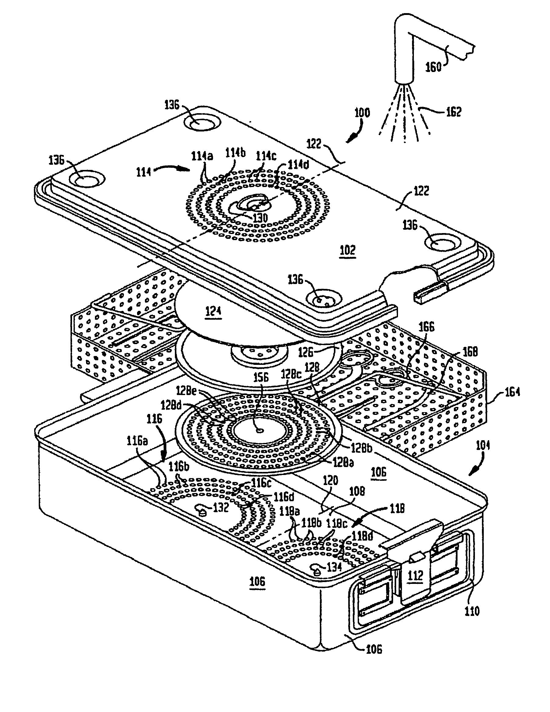
[0078] An embodiment 100 of the sterilization container apparatus modified for gas plasma is illustrated in the exploded view of FIG. 5, Panel A. The container 100 includes a top or lid 102 that sits on top of a bottom or pan 104. Bottom 104 includes four sidewalls 106 and a bottom or base 108. A pair of wire handles, or bales 110 are located on opposite ends of the bottom portion 104 and are held in place by a pair of lockable latches 112.

[0079] A first set of vent holes 114 is located in top 102. The vent holes 114 are preferably arranged as a group of four concentric circles with holes 114a, 114b, 114c and 114d in each, respectively. In all, the total number of holes may range from 100 to 500 and have a size that ranges in diameter from, but not limited to, about 3 / 16 inches to about 5 / 16 inches. The first set of vent holes 114 is located on the central axis 122 of the short dimension of the lid 102. The first set of vent holes 114 allows the sterilizing medium 162 to pass into t...

embodiment 200

[0086] This second alternative embodiment 200 also provides for improved circulation of the gas plasma through the container so as to contact all the surgical instruments and the corners of the device.

[0087] The preceding embodiments of a sterilization container may also be utilized to extend the length of time that its contents remain sterilized, particularly with use of thermostatic valve assembly 300. Use of thermostatic valve 310 and cover 320 prevents any contaminants from entering the container after it has been sterilized because thermostatic valve 310 closes as the internal temperature of the container declines. Once thermostatic valve 310 closes, the container will maintain its sterility and may be stored until use. The thermostatic valve assembly may also contain a mechanism for recording the opening or closing of the valve, which may provide to the user recorded evidence of proper valve function. In one embodiment, a pin or marker perforates or marks a record material, su...


PUM

PropertyMeasurementUnit
temperatureaaaaaaaaaa

Abstract

The invention relates to a container for sterilizing medical instruments and, in particular, to a sterilization container useful for flash sterilization that includes a thermostatically controlled valve that permits maximum steam or gas sterilant penetration and prevents microorganisms and dust from entering. The thermostatic valve also allows storage of sterilized contents and reduces moisture within the sterilization container.

Description

CROSS REFERENCE TO RELATED APPLICATIONS [0001] The present application is related to and claims, under 35 U.S.C. §119(e), the benefit of U.S. Provisional Patent Application Ser. No. 60 / 333,184, filed Nov. 16, 2001, which is incorporated herein by reference. This application is related to International Application PCT / US99 / 08949 filed on Apr. 8, 1999, and published under PCT Article 21(2) in English, which is a continuation-in-part of International Application No. PCT / US98 / 17671 filed on Aug. 22, 1998, and published under PCT Article 21(2) in English, which is a continuation-in-part U.S. application Ser. No. 09 / 023,055 filed on Feb. 12, 1998, now U.S. Pat. No. 5,968,459. The entire contents of all international and national patents and application disclosed herein are hereby expressly incorporated by reference.FIELD OF THE INVENTION [0002] The invention relates to a container for sterilizing medical instruments and, in particular, to a sterilization container useful for flash sterili...

Claims


Application Information

Patent Timeline
Patent Type & Authority Applications(United States)
IPC IPC(8): A61B19/02A61L2/00A61L2/07A61L2/14A61L2/20A61L2/26
CPCA61B19/02A61B19/0271A61B2019/0213A61B2019/0258A61B2019/0272A61B2019/0281A61L2202/24A61L2/14A61L2/20A61L2/206A61L2/26A61L2202/122A61L2/07A61B50/00A61B50/22A61B50/33A61B50/34A61B2050/006A61B2050/3011
Inventor FRIEZE, ALLANFRIEZE, MARCIAAMSTER, RON
Owner CASE MEDICAL
Why Eureka
Try Eureka