Low-power photonic telemetry system and method for spacecraft monitoring

a low-power, spacecraft-based technology, applied in navigation instruments, instruments, transportation and packaging, etc., can solve the problems of spacecraft not having adequate link margins, tumbling too quickly, and further complicating the telemetry problem, so as to achieve efficient and timely integration, reduce the effect of rf, and reduce the number of r

Inactive Publication Date: 2005-10-27
FIELHAUER KARL B +1
View PDF19 Cites 18 Cited by
  • Summary
  • Abstract
  • Description
  • Claims
  • Application Information

AI Technical Summary

Benefits of technology

[0013] It is another feature of the present invention to provide a small-sized, low-power, high-bandwidth photonic telemetry system and method that is compatible with wireless, infra-red (IR) busses, and extensible to pre-launch built in test (BIT) and ISS (International Space Station) BIT, and can be made secure using micro-electro-mechanical systems (MEMS) beam-steering, signal encoding, and wavelength division multiplexing.
[0014] It is a further feature of the present invention to provide a low power photonic telemetry system as an add-on launch service thereby standardizing the approach and interface.
[0015] It is yet another feature of the present invention to provide a telemetry system and method that does not produce significant RF and uses little power so that it is independent of battery charge state and can be used during the separation of a spacecraft from its launch vehicle, and which would not interfere with existing launch vehicle telemetry and beacon systems.
[0016] It is still yet a further feature of the present invention to provide a telemetry system and method with a sufficient link state so that the system can monitor tumbling spacecraft which could otherwise not be sufficiently monitored by RF transmitter / receiver pairs.
[0017] It is yet another feature of the present invention to provide efficient opto-coupled capability for pre-launch BIT on the ground, either during assembly or just prior to launch, to allow more efficient and timely integration and preflight checkout.

Problems solved by technology

To further complicate the telemetry problem, the frequency and number of upcoming launches of space vehicles is increasing.
Moreover, as the dates and times of interplanetary missions are target driven, and as event-driven telemetry systems can add significant cost to space missions, a more flexible telemetry architecture must be considered for interplanetary and event-driven launches.
In addition, the spacecraft may not have adequate link margin or may be tumbling too quickly under certain scenarios for RF telemetry to be received.
Furthermore, missions requiring constellations of spacecraft (nanosats) may not have an adequate number of ground assets to query all spacecraft during an initial pass.
However, the design of two RF systems: an S-Band system for separation and early operation, e.g., tracking and data relay satellite system (TDRSS), and another X-Band or Ka-Band system needed to support the mission, may not be practical or possible for all missions.

Method used


Image

  • Low-power photonic telemetry system and method for spacecraft monitoring
  • Low-power photonic telemetry system and method for spacecraft monitoring
  • Low-power photonic telemetry system and method for spacecraft monitoring

Examples


second embodiment

[0019] In accordance with the present invention, an optical communication system for relaying data is provided comprising an optical transponder for transmitting an interrogation beam and receiving a retransmitted interrogation beam, the optical transponder being mounted on a first vehicle; and a spatial light modulator (SLM) transponder for receiving the interrogation beam, adding data to the interrogation beam and retransmitting the interrogation beam, the SLM transponder being mounted on a second vehicle; wherein the first vehicle obtains status and location information of the second vehicle from the retransmitted interrogation beam.

third embodiment

[0020] In accordance with the present invention, an optical telemetry system for space vehicles is provided comprising an optical source for providing an optical signal for interrogation, the optical source being mounted on a first vehicle; a receiver for receiving the optical signal, the receiver being mounted on a second vehicle; a modulator coupled to the receiver for modulating the received optical signal; a transmitter coupled to the receiver for transmitting the modulated optical signal; and a receiving device for receiving the modulated optical signal, the receiving device being mounted on the second vehicle.

fourth embodiment

[0021] In accordance with the present invention, a method for obtaining data including location and status of a vehicle is provided comprising querying a first vehicle from a second vehicle using an interrogating beam; modulating the interrogating beam so that it contains information about the first vehicle and re-radiating the modulated interrogating beam; and receiving and demodulating by the second vehicle the modulated interrogating beam.

BRIEF DESCRIPTION OF THE DRAWINGS

[0022] The above and other objects, features and advantages of the present invention will become more apparent from the following detailed description when taken in conjunction with the accompanying drawings, in which:

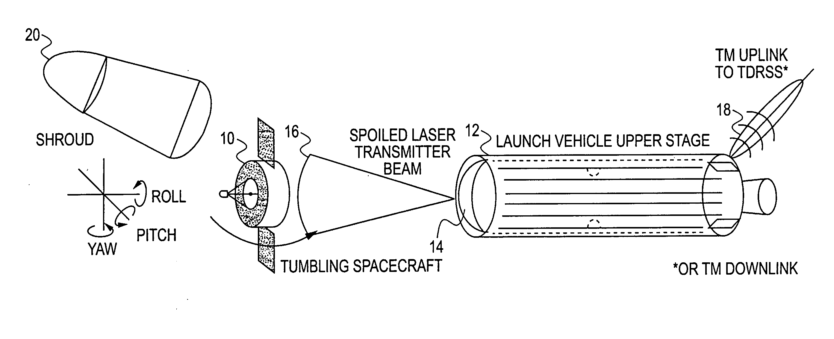
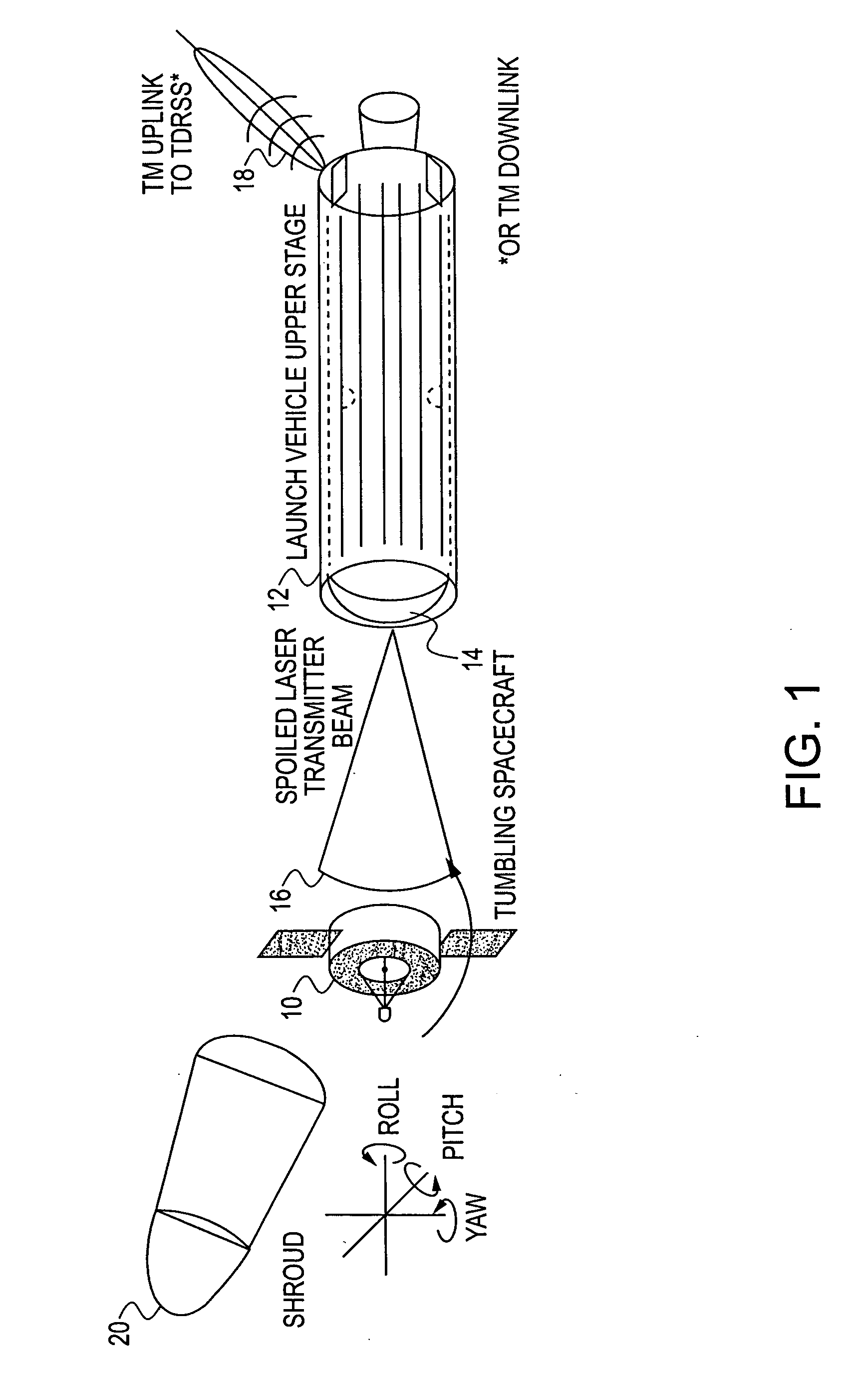
[0023]FIG. 1 illustrates an optical spacecraft telemetry system according to an embodiment of the present invention;

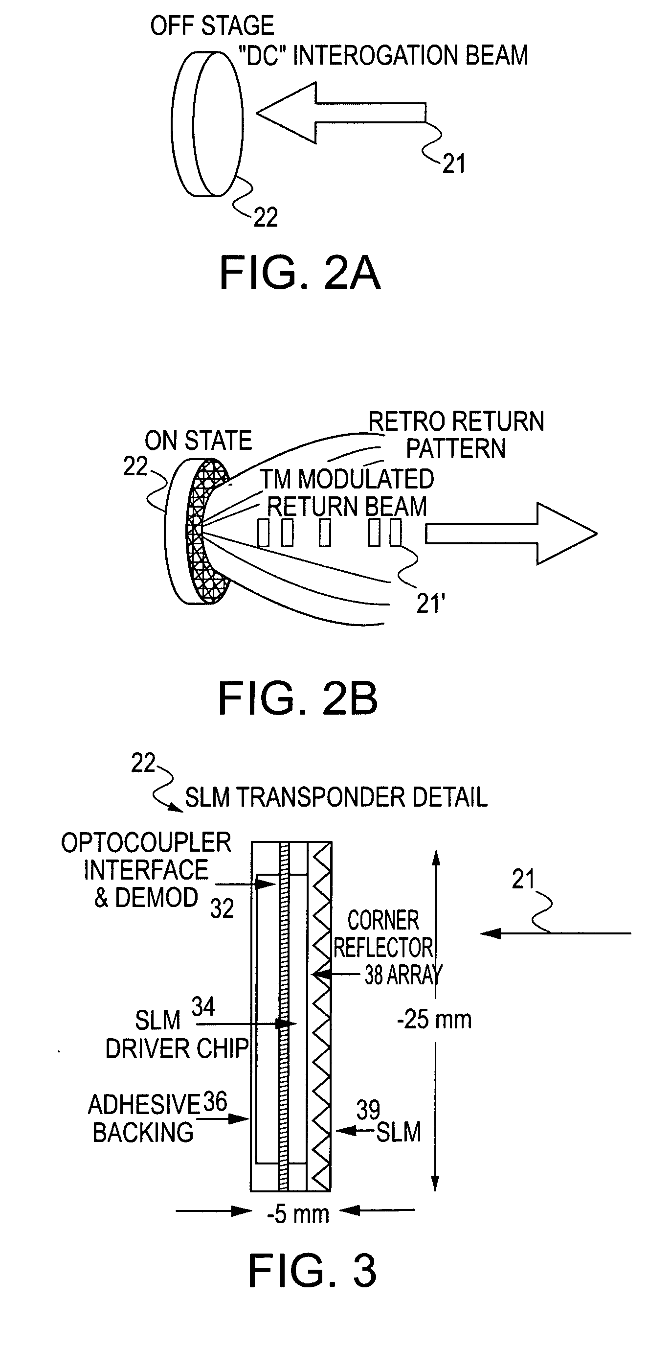
[0024]FIGS. 2A and 2B illustrate the operation of a spatial light modulator (SLM) transponder which is queried by a DC interrogation beam according to an embodiment of the present i...


PUM


Abstract

An optical telemetry system and method for monitoring the location and status of a spacecraft (e.g., a satellite, a missile, a manned vehicle, etc.) using an optical communication link in an extraterrestrial environment. The system is optimally suited for monitoring the status and location of the spacecraft during a separation procedure of a spacecraft from its launch vehicle and uses a low-power optical communication link between a support craft and a spacecraft to obtain data. The data is then processed by the support craft and relayed to sources external to the support craft using the launch vehicle's telemetry system. Moreover, the system and method can also be used to monitor the status and location of an array (e.g., a three-dimensional array) of space vehicles traveling in space (e.g., an array of satellites).

Description

CROSS-REFERENCE TO RELATED APPLICATIONS [0001] This application claims the benefit of prior filed co-pending U.S. application No. 60 / 516,780, filed on Nov. 3, 2003, the contents of which are incorporated herein by reference.STATEMENT OF GOVERNMENTAL INTEREST [0002] This invention was made with Government support under Contract No. NAS5-97271, awarded by the National Aeronautics and Space Administration (“NASA”). The Government has certain rights in the invention.BACKGROUND OF THE INVENTION [0003] 1. Field of the Invention [0004] The present invention relates to an apparatus and method for monitoring spacecraft location and status using an optical communication link in an extraterrestrial environment, and more particularly to an apparatus and method for monitoring the status and location of a spacecraft during separation from its launch vehicle using a low-power optical communication link to obtain data and then relaying the data using an existing launch vehicle telemetry system as a...

Claims


Application Information

Patent Timeline
Patent Type & Authority Applications(United States)
IPC IPC(8): B64D3/00G01C15/00
CPCG01C15/002
Inventor FIELHAUER, KARL B.BOONE, BRADLEY G.
Owner FIELHAUER KARL B
Why Eureka
Try Eureka